Continue to Site

Eng-Tips is the largest engineering community on the Internet

Intelligent Work Forums for Engineering Professionals

  • Congratulations waross on being selected by the Eng-Tips community for having the most helpful posts in the forums last week. Way to Go!

Composite Position and Parallelism 2

Status
Not open for further replies.

gregkeez

Mechanical
Feb 28, 2022
6
Hello,

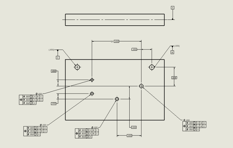
First time posting on here. I'm working on a drawing with a group of holes that I want to control as a pattern using composite position. In the feature control box, the goal of the second line is to control the pattern's parallelism to the two datum holes. Is this the correct way of doing such or would it be something like A | B-C in the feature control box?? The actual part I am working on is not a simple rectangular shape, rather something a little more complex but I figured this was good enough to get my point across. I know I could add another datum to say, the top of the part and have parallelism to that but was wondering if I could do the same thing using composite position.

Composite_Position_jxw0v4.png
 
Replies continue below

Recommended for you

gregkeez,
The approach with B secondary and C tertiary in the second segment of the composite FCF is correct in this case.

I see that all the composite FCF on the drawing have indetical tolerance values between orresponding segments, therefore you may want to consider labeling each of the toleranced holes with a letter, say D, and then just using a single composite FCF supplemented with notation HOLES INDICATED D.
 
pmarc,

Why do you need B and C in the second/ middle segment? What degrees of freedom of the tolerance zone those two datums (B and C) will stop.
I don't remember much about the composites in ASME, but I do remember that the FRTZF should stop only the rotation DOF's.
 
greenimi,

This would be rotation about datum axis B.
 
pmarc said:
This would be rotation about datum axis B.

So how the rotation around B (or C for that matter) is going to be stopped, IN SHOWN configuration?

 
greenimi,
I am not sure I understand your last question.

The purpose of having B and C in the second segment is to orient/constrain rotation of the pattern of tolerance zones relative to the line connecting axes of datum feature simulators B and C.
 
pmarc


pmarc said:
The purpose of having B and C in the second segment is to orient/constrain rotation of the pattern of tolerance zones relative to the line connecting axes of datum feature simulators B and C.
There is no B-C in the composite. It is B secondary and C tertiary.

It is not common datum feature B-C.
I am trying to not violate the datum feature precedence, as written on the drawing

 
Thank you for your input! Another question, considering three of the holes have BASIC's from the first hole which has BASIC's to datum B, would I be correct in adding the "SIM REQT" for all the holes?
 
gregkeez said:
Thank you for your input! Another question, considering three of the holes have BASIC's from the first hole which has BASIC's to datum AC, would I be correct in adding the "SIM REQT" for all the holes?

Let pmarc answer first my question, please.

He is the best around here and I am trying to leran something from him from this discussion.

Then, we will address your follow up question. Fair game?

 
Absolutely, I'm trying to learn as well!
 
gregkeez,
You don't have to indicate SIM REQ, it is applied by default on the upper segments of the composite position tolerances because the same datum references in the same order of precedence are specified in those segments.
 
greenimi,

It does not have to be B-C to be able to imagine a line that connects the axes of the two simulators. The line is just an aid to visualize a horizontal reference that stops rotation of the pattern of tolerance zones.

The difference between B-C and B|C will manifest in different part-to-simulators relationship, but that is a separate topic, I would say.
 
pmarc said:
It does not have to be B-C to be able to imagine a line that connects the axes of the two simulators. The line is just an aid to visualize a horizontal reference that stops rotation of the pattern of tolerance zones.

If I am decoding A|B|C| in this order of precedence (as currently specified in the FCF) for the holes / features which are nominally parallel with B and C, for sure I would say that B and C in the FRTZF (second segment) will have no purpose. Both of them are not able to arrest any DOF's. (if I am wrong, please correct me).

Now, if you are changing "the game" and use B-C (as secondary) then I agree with your assessment above.

Am I missing something? Or I am too far entrenched in theory?

 
greenimi, out of 3 rotational DOF, datum feature simulator A as the primary constrains two.
The third is not constrained until C comes into play as tertiary, because B as secondary allows rotation about its axis.
 
Burunduk said:
The third is not constrained until C comes into play as tertiary, because B as secondary allows rotation about its axis.

So looks like A|B-C| is the appropriate datum scheme in this case not A|B|C|.
Due to the configuration of the features on this part, does not look like you guys agree that A|B|C| could be used at all.....
Am I correct?

 
I did not say that A|B|C was not appropriate.

Of course, I am intentionally ignoring the fact that in the OP's example the datum holes are threaded. If we add this to the equation, I will take a risk and say that neither B-C nor B|C makes sense.
 
I don't see any issues with A|B|C either. There is nothing problematic with how the degrees of freedom are constrained.
 
pmarc said:
I did not say that A|B|C was not appropriate.

I think we are going in circles here. If A|B|C| is the way to go then I might have an issue with the "violation of datum feature precedence" in the second segment of the composite.
The theroy says that B and C do nothing.

I am still trying to see and understand what you are saying in this quote

pmarc said:
"It does not have to be B-C to be able to imagine a line that connects the axes of the two simulators. The line is just an aid to visualize a horizontal reference that stops rotation of the pattern of tolerance zones.
The difference between B-C and B|C will manifest in different part-to-simulators relationship, but that is a separate topic, I would say."
 
greenimi,

Sorry, but apparently today is not a good day for us to communicate, as I have no clue why you think that |A|B|C| in the second segment of composite is a "violation of datum feature precedence".

Does it have anything to do with a belief that repetition of the same datum features in the lower segment of composite FCF as specified in the uppermost segment is not allowed?
 
Status
Not open for further replies.

Part and Inventory Search

Sponsor