Continue to Site

Eng-Tips is the largest engineering community on the Internet

Intelligent Work Forums for Engineering Professionals

  • Congratulations waross on being selected by the Eng-Tips community for having the most helpful posts in the forums last week. Way to Go!

Composite Position and Parallelism 2

Status
Not open for further replies.

gregkeez

Mechanical
Feb 28, 2022
6
Hello,

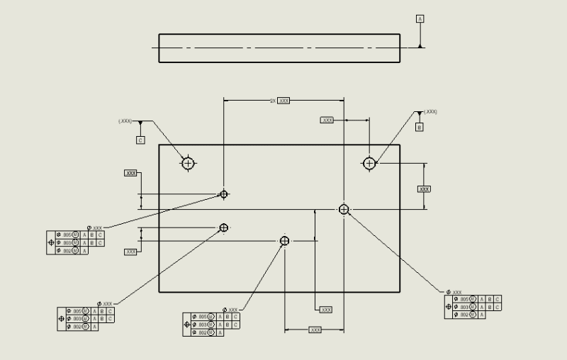
First time posting on here. I'm working on a drawing with a group of holes that I want to control as a pattern using composite position. In the feature control box, the goal of the second line is to control the pattern's parallelism to the two datum holes. Is this the correct way of doing such or would it be something like A | B-C in the feature control box?? The actual part I am working on is not a simple rectangular shape, rather something a little more complex but I figured this was good enough to get my point across. I know I could add another datum to say, the top of the part and have parallelism to that but was wondering if I could do the same thing using composite position.

Composite_Position_jxw0v4.png
 
Replies continue below

Recommended for you

Imagine if datum feature B was manufactured as slot-shaped right-to-left and datum feature C was manufactured slot shaped up-and-down, allowing the RFS datum reference frame to rotate.
 
axym said:
But I've found that this interpretation is probably in the minority. A lot of people have arrived at a different interpretation that is similar to what greenimi described - that the lower segment datum features act differently and only constrain rotational DOF's.

Thank you very much Evan for your writeup. I appreciate your clarity and how you explained the right interpretation (and correct my missunderstandings and my wrong interpretation).
Thank you Burunduk for your contribution


axym said:
This shows what Burunduk described. The 0.4 mm upper segment zones (PLTZF) are centered on the true profile, they have not translated. The 0.2 lower segment zones (FRTZF) have translated downward to optimize the actual value. The little red arrow above the 10 mm basic dimension represents how far they translated.

There's a fundamental understanding I'm lacking -- if the tolerance zone is allowed to move at all relative to the original nominal location of the true profile, why not rotate it as well instead of translating only in the "Y" direction as illustrated? And if it can rotate and translate--what are referencing datums B and C even adding to the interpretation? Would omitting them mean anything different?
 
BiPolarMoment,
The tolerance zones of the FRTZF are only allowed to translate, not rotate, because this is how lower segments of the composite feature control frames work by definition.
 
I think we should let 3DDave explain what he meant, but I don't think he said that the tolerance zones of the FRTZF were allowed to rotate relative to the A|B|C DRF in Evan's figure.
 
BiPolarMoment said:
if the tolerance zone is allowed to move at all relative to the original nominal location of the true profile, why not rotate it as well instead of translating only in the "Y" direction as illustrated?

The idea of composite tolerancing is that you tighten the requirement of orientation to the referenced datums in the lower segments (and the mutual relationship between the grouped features) while allowing a larger location tolerance relative to the datum reference frame established from the datum references in the top segment. That's why the tolerance zone framework for the lower segments is only allowed to translate, but not rotate, relative to the referenced datums.
 
What I meant - draw the datum feature B as a slot that is horizontal and the datum feature C as a slot that is vertical

then the part is not locked into position the way the math standard appears to show is the guaranteed result.

When the simulators expand into the slots they would make contact at only two points and cannot expand any more. They are free to translate in the slots, meaning the part is able to move relative to the datum feature simulators and the features being investigated would be free to move relative to the defined tolerance zones.

In addition, datum feature B wouldn't constrain the part in the x direction - that is done by datum feature C.

The combination in the example doesn't always prevent all rotation - the part can still rotate.

The cure is to require a cylindricity tolerance that is smaller than the measuring capability of the CMM, which poses something of a problem. In order to avoid the case where two or more "expansion" solutions exist the feature must be more precise than the CMM ability to detect those solutions.

I expect the typical solution is to simply pick 3 points in the first hole and only 2 in the second one, which does not meet the math standard requirement and may not meet the installed condition for the part.
 
What this describes is a special case of datum feature geometry that may lead to rotation of the part relative to the DRF established from the datum feature simulators. It still doesn't mean that the tolerance zones of the FRTZF are free to rotate relative to the DRF.
 
"It still doesn't mean that the tolerance zones of the FRTZF are free to rotate relative to the DRF. "

How do you get that assertion from "the part is able to move relative to the datum feature simulators"
 
Simply because you haven't proved otherwise. All you proved is that under certain special condition the part is able to move relative to the DRF.

It is similar to a simple case where a parallelism tolerance wrt datum plane A is applied to a surface located at a distance from A, and the as produced datum feature A turned out to be convex (a rocker). The part will be allowed to rock (when 2009 or earlier standard is in charge), but the parallelism tolerance zone will still need to be parallel to the datum feature simulator A while being able to translate relative to A.
 
What leads you to believe I was trying to prove otherwise?

How do you get that assertion from "the part is able to move relative to the datum feature simulators"

The example gives unneeded detail to "prove" that the expanding simulators are always going to work. This is misleading.

It's like how the "tangent" modifier is always exemplified against a non-purely convex surface to show that it only has a stable solution when it clearly won't always be.
 
Hi All,

The scenario that 3DDave brings up is not a typical case, but we have to acknowledge that it is possible. If the datum feature holes were produced with a slotted condition, then there would be residual datum feature shift even though the holes are referenced RMB. This is an unfortunate reality with almost any type of datum feature specification - we can think of pathological as-produced geometry that will defeat the intended degree of freedom constraint. Applying form tolerances to the datum features puts a limit on the magnitude of the shift, but doesn't eliminate it entirely. A nominally planar surface can always be produced convex or v-shaped within the flatness tolerance, nominally cylindrical holes can always be slotted within their cylindricity tolerance, nominally cylindrical pins can be produced tapered within their cylindricity tolerance, etc. If a stable DRF is an absolute requirement, then we need to specify some sort of datum target configuration instead of full TGC's.

The detail in the example was not intended to prove that expanding simulators are always going to work. It was intended to illustrate the constraint that would occur in the large majority of cases. I would say that if unusual as-produced features with pathological properties were shown instead, then that would be misleading.

Evan Janeshewski

Axymetrix Quality Engineering Inc.
 
3DDave,

I just think it would be easier for everyone (especially BiPolarMoment in this particular situation) if you just focused on helping people understand basic stuff instead of asking me how I got to my assertions based on what you had said about a problem that is interesting (no doubt) but also distracting.

BiPolarMoment clearly stated he/she was confused by your first mention about slotted holes in the context of allowable movement of the FRTZF. I replied for you that you didn't mean to say that the FRTZF was free to rotate relative to the DRF. You have just never confirmed that.
 
Status
Not open for further replies.

Part and Inventory Search

Sponsor