Eng-Tips is the largest engineering community on the Internet

Intelligent Work Forums for Engineering Professionals

Composite Position Tolerance for Hole pattern.

Status
Not open for further replies.

ASHWA

Automotive
Oct 7, 2020
52
0
0
IN
Dear All,
Have a doubt Composite Position Tolerance,

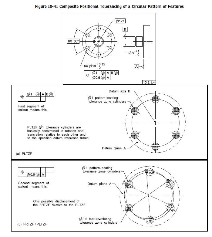
zz_qdswq9.jpg


In this PLTZF,
WW_vyejsh.jpg


It's given B(M), this secondary datum is referenced for Axis.

Does giving B(M), can vary the positioning of Hole pattern?

If the DATUM B, is given with position tolerance, it would make a shift in Hole Patten - but not given.

Kindly reply,

Thanks.
 
Replies continue below

Recommended for you

ASHWA,

It sounds like you're asking if B(M) ie: B referenced at MMB provides additional position tolerance. The correct answer is no, MMB (Maximum Material Boundary) provides datum feature shift but is NEVER a bonus tolerance. It might look like a bonus tolerance, but their behavior is markedly different - although in stacks it will often have to be considered for things like minimum/maximum wall thickness etc..

For a good example for the difference between the two take a look at the below thread and attached figure from CH on the referenced thread. It provides an excellent example for what MMB is and is not for a basic case.

 
Datum B referenced with the maximum material boundary modifier permits a shift of the location of the entire pattern as a whole relative to the datum B axis as datum feature B departs from its maximum material boundary (which is unknown in this example because it's a partial definition on purpose, missing a perpendicularity requirement of datum feature B relative to datum A). The shift would equal the amount of datum feature B's related actual mating envelope's departure from the MMB condition. No shift would be available if datum feature B was produced at its maximum material boundary.
 
Burunduk said:
Datum B referenced with the maximum material boundary modifier permits a shift of the location of the entire pattern as a whole relative to the datum B axis...
A minor correction to the terminology -- the pattern of holes will not shift relative to datum axis B, but it will shift relative to the actual axis of datum feature B's AME.

John-Paul Belanger
Certified Sr. GD&T Professional
Geometric Learning Systems
 
Belanger, I completely agree with your correction. Thank you.
A clearance between datum feature B and the datum feature B simulator from which the datum axis is derived can be used to shift the part on the fixture and bring the pattern of holes into their tolerance zones pattern - which is fixed relative to the datum axis. Hence the pattern of holes doesn't shift relative to the datum, it shifts relative to the datum feature (the "shift" is between the location of the pattern in the condition described and its passing location relative to the datum feature's B related AME axis at the RMB scenario).

By the way, see this tip:
from Tec-Ease

"When datum features are modified at MMB or LMB, the datum feature and the features being controlled may be able to shift relative to the datum axis or centerplane"

I think they made a similar mistake as I did above, didn't they?
 
No, that terminology seems correct (the datum feature can displace from the datum, and the features being controlled can also deviate from the datum).
The only thing I can spot on that tip is that they forgot to use the leading zero in front of a couple of the .2 tolerances.

John-Paul Belanger
Certified Sr. GD&T Professional
Geometric Learning Systems
 
Belanger, sorry for my confusion but:

Your initial statement:
"the pattern of holes will not shift relative to datum axis B but it will shift relative to the actual axis of datum feature B's AME."

The tip:
"When datum features are modified at MMB or LMB, the datum feature and the features being controlled may be able to shift relative to the datum axis or centerplane"

Since the tip and the question being asked in this thread deal with the same concept,
Are you sure there is no terminology problem at the tip?

Your last statement:
"the datum feature can displace from the datum, and the features being controlled can also deviate from the datum"

I'm not sure what you mean by "deviate from the datum". I think they cannot deviate from the tolerance zones, which are fixed relative to the datum, at least in the case shown in the tip or for the upper segment of a composite control.

My initial understanding of your comment was that since the tolerance zones of the pattern (in the top segment) are basically constrained to the datum axis, and the axes of the features being controlled must fit in those tolerance zones (in terms of the axis interpretation), then the features cannot really shift relative to the datum, but they can shift relative to the datum feature. The mobility of the datum feature relative to the datum axis can accommodate this.

In my opinion, the term "shift" as referred to in the standard describes the ability of the datum feature to move relative to the datum/datum reference frame, and effectively this allows some displacement of the features being controlled relative to the datum feature (but not the datum), which isn't available with the datum referenced at RMB. Where am I wrong?

 
Sorry for the confusion. The pattern of holes may of course shift from the datum because that's the point of assigning a position tolerance. It that case I'm not using shift in the sense of "datum shift," but merely of regular displacement due to the given tolerance (plus any bonus). At the same time, because of the MMB modifier the datum feature may displace from the datum, perhaps in the opposite direction. This is the specific "datum shift."

Put those two ideas together, and the actual location of the holes can be quite a bit off from the datum feature's axis.

So what I meant is that we cannot say that the pattern of holes gets extra shift away from datum B due to the MMB modifier. But it will get extra shift away from datum feature B due to the MMB modifier.

John-Paul Belanger
Certified Sr. GD&T Professional
Geometric Learning Systems
 
Belanger,
Thank you for the clarification and I completely agree.

I still don't agree with the wording in the Tec-Ease tip, because if the "shift" of the holes pattern relative to the datum is only a regular displacement due to the given tolerance (plus any bonus), then saying "When datum features are modified at MMB or LMB, the datum feature and the features being controlled may be able to shift relative to the datum axis or centerplane" is misleading. The features being controlled can shift the same amount of displacement relative to the datum axis or center plane without the MMB/LMB modifier applied to the datum references.
Considering your statement that; "we cannot say that the pattern of holes gets extra shift away from datum B due to the MMB modifier", don't you think the same?
 
I suppose by being so careful to use the the correct terminology, we got ourselves down a little rabbit hole. But I do see what you're saying.
The Tec-Ease wording isn't blatantly wrong, but yes it may be misleading in the sense that you mentioned. Perhaps breaking it into two statements would have been better:

"The features being controlled may always shift relative to the datum axis or centerplane based on the given tolerance (plus any bonus)."
"When datum features are modified at MMB or LMB, the datum feature may also shift relative to the datum axis or centerplane."

That keeps the MMB/LMB idea specifically tied to the datum feature's variation.

John-Paul Belanger
Certified Sr. GD&T Professional
Geometric Learning Systems
 
Belanger, your altered wording broken into two statements is precise and it is much preferred as far as I'm concerned.

As you mentioned:

"That keeps the MMB/LMB idea specifically tied to the datum feature's variation."

And I would add - also to the resultant additional variation the controlled features as a group are allowed relative to the datum feature; Specifically relative to the related actual mating envelope of the datum feature (which would serve as the datum feature simulator / true geometric counterpart had the datum reference been at RMB).
 
I'm curious, in this example, a go/no-go gauge would be a block with a Ø51 hole and a pattern of 6X Ø18 pins located basically from the Ø51 hole. The only relevance of establishing the location of datum axis B is in relation to the hole pattern correct? So the simulated datum axis B would be the axis of the Ø51 hole of the go/no-go gauge. However, there wouldn't be a way to getting a datum axis from the part itself correct?
 
Supertrucker -- technically this print is missing a tolerance that relates datum feature B to datum A; there should be a perpendicularity tolerance. Then we can identify the size of the hole needed in the functional gage. But if we presume the perpendicularity tolerance is zero at MMC, then yes the hole would be Ø51.

You asked: "The only relevance of establishing the location of datum axis B is in relation to the hole pattern correct?" Well... there is no location needed for datum axis (or datum feature) B simply because it is the driving factor that everything else is located from.

And to your last question: "there wouldn't be a way to getting a datum axis from the part itself correct?" The datum axis is created from what is called the "related actual mating envelope" of that center post. It all boils down to the idea that a datum is something that's perfect, but it has to somehow be derived from something on the part which is imperfect.

John-Paul Belanger
Certified Sr. GD&T Professional
Geometric Learning Systems
 
Belanger, if the datum axis is created from the related actual mating envelope of the center post, which I understand to be the smallest cylinder perpendicular to datum A that would touch the high points of the datum feature (assuming a perpendicularity tolerance), what happens in the case of datum shift since it allows the datum feature to shift away from the datum axis? The rAME would establish the axis of the datum feature, but if it is shifted away from the datum axis because of datum shift, is there still a way of getting the datum axis from the part?
 
Yep -- good catch. Since B is referenced at MMB, then I should have said that the datum axis is created not from a collapsing envelope, but from a perfect cylinder of Ø51 (again, assuming that there's a perp tolerance of zero at MMC) that is exactly perpendicular to datum plane A. Thus, depending on the actual part's R.A.M.E., then may be as much as 1 mm of datum shift.

John-Paul Belanger
Certified Sr. GD&T Professional
Geometric Learning Systems
 
superptrucker,
To your question on getting a datum axis "from the part itself" versus using the gage for this purpose, let me give you a direct quote from the ASME Y14.5 standard:

" The datum reference frame is established
from the true geometric counterparts and not from the datum features."

This by the way is true both for datum features referenced at MMB/LMB AND for RMB. The only difference is that in the RMB case the adjustable-size datum feature simulator/TGC would need to expand/contract to engage with the datum feature and make contact as fully as possible while respecting datum precedence order.

If we had to derive the datum axis from the actual part itself we would not be able to make inspection fixtures before having the part on-hand.
 
Status
Not open for further replies.
Back
Top