Continue to Site

Eng-Tips is the largest engineering community on the Internet

Intelligent Work Forums for Engineering Professionals

  • Congratulations waross on being selected by the Eng-Tips community for having the most helpful posts in the forums last week. Way to Go!

Composite Position With No Exterior Datums

Status
Not open for further replies.

edw.jack23

Industrial
Jun 22, 2022
8
A customer has given us free reign to pick our Datums since the drawing they provided had ones that were not GD&T compliant. They want true position of bosses in a pattern. My question is can the datums be within that pattern, i.e the bosses themselves. I don't like how we have it set up now (see attached for rough sketch) because it does not relate the pattern to the rest of the part at all so there's no telling if the entire pattern is rotated in relation to the rest of the part. Is this a non-compliant call out?
[URL unfurl="true"]https://res.cloudinary.com/engineering-com/image/upload/v1655906281/tips/2022-06-22_7-54-30_nhtgyu.pdf[/url]
 
Replies continue below

Recommended for you

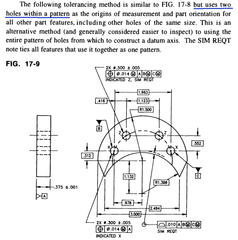
If I understand your question correctly, this is an example for your reference (snapshot from James D. Meadows' book "Geometric Dimensioning and Tolerancing: Applications and Tolerances for Use in Design, Manufacturing and Inspection").

2022-06-22_084935_fssk4k.jpg


Season
 
I think that it does not. My question is basically this: In a composite position tolerance, do the datums have to be outside the pattern of features?
My feeling is yes, because otherwise the PLTZF doesn't really work, the pattern location references itself, but I can't find any hard answer on that anywhere. All of the composite ASME examples are from datums outside the pattern, but it does not say that that is a requirement.
 
edw.jack23,
If the cylinders are used as datum features the rest of the part could be controlled by profile tolerances with reference to the datum feature A surface and these B and C datum feature cylinders and that is what would govern the mutual orientation between the pattern and the part outline.

The easier and perhaps less controversial way to do what you are doing would be to use two separate position tolerances, one for the two holes used as datum features B and C, and it would reference A only. You could refine it by a perpendicularity tolerance. The other position tolerance would be as you have shown but it would apply to the rest of the cylinders (5X and not 7X).
 
Status
Not open for further replies.

Part and Inventory Search

Sponsor