Eng-Tips is the largest engineering community on the Internet

Intelligent Work Forums for Engineering Professionals

Composite Position

Status
Not open for further replies.

2020Learner

Automotive
Jun 27, 2021
19
0
0
HK
Query_Composit_Position_funy9r.png


Hello Team,

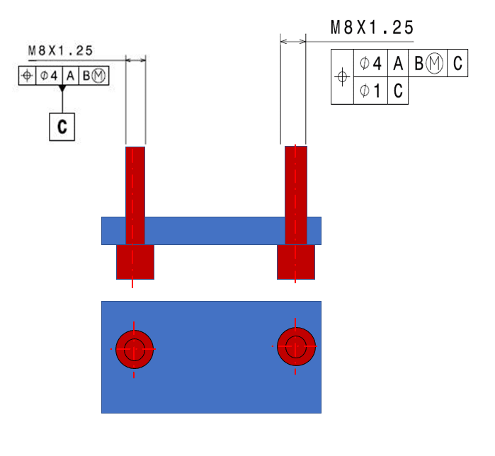
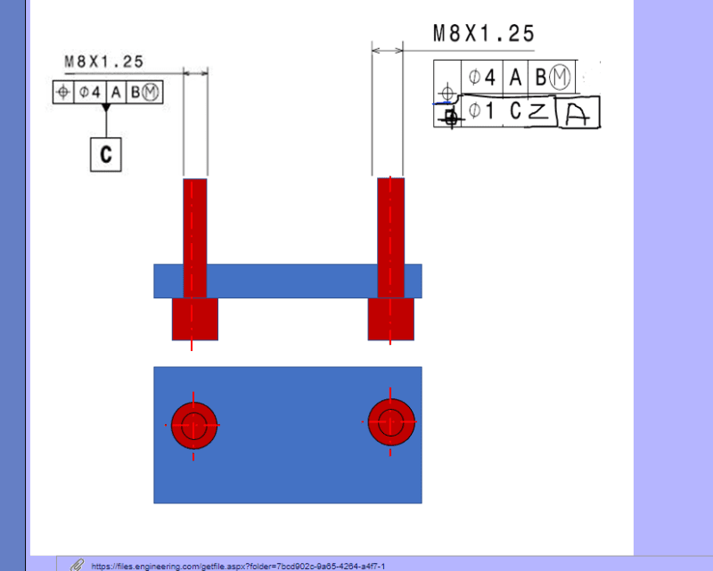
I have one doubt regarding composite position tolerance- Inserted picture.

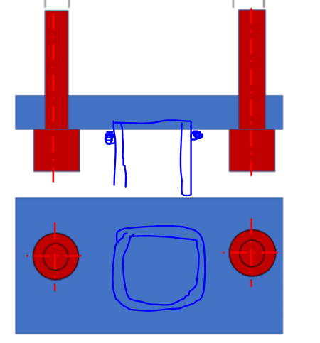
This is an Assembly where Datum A & Datum B is at inlet side and I shown picture at only other end where we can see Datum C is applied to one of the stud in the flange.
Other single stud is controlled with composite positional tolerance with respect to Datum C, which is applied to other Stud.

What I know from my experience is that Composite tolerance is applicable for pattern, so here we have two stud, one is Datum C and for single stud is applied with Composite position.
I felt it is wrongly interpreted here, lower segment is controlled with Datum C in composite frame. Can you all agree or do we have anything like this in ISO application or etc.?

Query_Composit_Position_rthimq.png
 
Replies continue below

Recommended for you

I don't think ISO has composite position.
Also, even if composite is changed to multi single segment, looks very weird to have tertiary C in the first segment and primary C in the second segment.
Just incorrect
 
Hello Greenimi,

Thank you for reply.
I agree with you it is not correct.
But Do you think, if we convert composite to single segment and if I use only top row with Datum C, will it be a wrong decision?
As this Flange Assy will get weld to inlet Assembly through pipe- connection.

Thanks,
 
I think you should keep the top segment: position Ø4 |A|B(M)|, and
the second segment to be changed to position Ø1 CZ|A|
Remove datum feature C symbol entirely and the second segment (position Ø1 CZ|A|) will take take care of the mutual relationship between the two pins.
 
Hi Greenimi,

I updated as per your comment
10-2-2022_ccjtqj.png


Datum C is contributing to arrest last rotation about X axis. Datum A, B is faraway from Datum C.
By Holding one pin as datum C, all DOF will be arrested.

Now i want to measure other pin with respect to all 3 datums so we have coarse value 4 (same value 4 as datum C pin)when we consider Datum C.
Do you thing it is difficult to achieve value 4 for other pin when we consider datum C (as Datum C pin has also position tol. 4) for top segment?.
For second segment, Datum A is far away from Datum C, do you think, can we achieve value Dia-1CZ with respect to Datum A?
 
Then maybe the left pin to be defined "as-is" (position at A|B(M)| ---and to become datum feature C) and the right pin to be defined only to C (something like position Ø1 to C).
That would be solution #2
(solution #1 is the one described above--previous replies)


I am wondering if in ISO is acceptable to use datumless position: something like this:
The right pin:
top position Ø4|A|B(M)|C|
bottom position Ø1 CZ

Pmarc,
If you read this discussion, could you, please clarity if my latest statement is correct in ISO?

 
greenimi,

I don't see how a position tolerance with no datum feature reference applied to a single feature could work, both in ISO and ASME. Addition of "CZ" in the tolerance frame does not look correct to me too.

From the OP's description, I am afraid I don't fully understand the function of the assembly. From the design standpoint, could both threaded studs be controlled with just a single position tolerance |POS|dia. 4 CZ|A|B(M)| without making one of them a datum feature for the other? Or would that define too generous tolerance for the mutual relationship between them? Also, shouldn't the studs be directly controlled for perpendicularity relative to the face from which they stick out? Just asking...
 
Hello Pmarc and greenimi

Thank you for comments.

To Pmarc,

Image_12-2-2022_nqvxtp.png


Background information
Actually my sketch is little incomplete information.
This is outlet end , This is flange assembly having two pressed stud is getting connected to pipe with welding like below image and this pipe goes long with other components attached towards inlet side where we have similar Flange Assembly where we have defined Flange face as Datum A and one pin as Datum B

for your first proposal, i agree to hold both pin controlling with position with respect to Datum A & B as this is Flange assembly comes with two studs.
But one worst case is, after we weld this flange assembly (OD welding or ID Welding with pipe) There is a risk to have concave shape in the flange where it will disturb the pin location or orientation between each other.

One more your last suggestion will works i think ie. is

if we define flange face as Datum D (Local datum) and then if we control position of one stud with respect to datum A & B and lower segment with tighter orientation tolerance with respect to datum D and making this as datum C and then other stud can be controlled with position respect to Datum C & D
 
Pmarc,
So looks like what the OP wants is only the relationships between the pins.

Pmarc said:
I don't see how a position tolerance with no datum feature reference applied to a single feature could work, both in ISO and ASME. Addition of "CZ" in the tolerance frame does not look correct to me too.

But there no single feature applied to. There are two of them.

Will this works then?
2x
top position Ø4|A|B(M)
bottom position Ø1 CZ


Again, intentionally I am ingoring for the moment perpendicularity
""""""
Also, shouldn't the studs be directly controlled for perpendicularity relative to the face from which they stick out?""""""""""
 
OP said:
if we define flange face as Datum D (Local datum) and then if we control position of one stud with respect to datum A & B and lower segment with tighter orientation tolerance with respect to datum D and making this as datum C and then other stud can be controlled with position respect to Datum C & D

I think what you are proposing is way too complicated and also does not look like the design intent. What is so special about left pin to be called datum C?
A simple solution could be achieved, but I am not really sure why datumless position does not work in ISO so I do need pmarc's help here.....
I think however datumless position works just fine in ASME.
 
greenimi,
Your previous proposal was this:

The right pin:
top position Ø4|A|B(M)|C|
bottom position Ø1 CZ

so I thought you wanted to apply datumless position to a single feature.

Your latest proposal, where the callout applies to two features, looks OK as far as the datumless position goes. However, the upper segment still needs CZ to create a pattern of two dia. 4 tolerance zones from the specification.
 
Pmarc said:
Your latest proposal, where the callout applies to two features, looks OK as far as the datumless position goes. However, the upper segment still needs CZ to create a pattern of two dia. 4 tolerance zones from the specification.

Ok. Understood. I missed that removing tertiary C in the top segment will leave one non - redundant DOF open, hence CZ is needed to create the desired pattern.

Now, just a quick follow up: I think adding D in the lower segment will take care of the previously (intentionally) ignored perpendicularity, doesn't it?

2x
position Ø4 CZ |A|B(M)
bottom position |Ø1 CZ |D|

OP said:
if we define flange face as Datum D (Local datum) and then if we control position of one stud with respect to datum A & B and lower segment with tighter orientation tolerance with respect to datum D and making this as datum C and then other stud can be controlled with position respect to Datum C & D

Does it look good in your perspective (with what we know so far about this welded assembly)?


Hi greenimi,

I will keep this proposal as one solution, all together i will consider as Datum C and one more is my proposed (below )

Solution-1
2x
position Ø4 CZ |A|B(M)
bottom position |Ø1 CZ |D|

Solution-2
We have few standard examples like this second solution.
My_solution_qpmjgj.png


Thank you pmarc and Greenimi
 
greenimi,

Yes, adding D in the lower position callout will take care of the perpendicularity. It will also refine the spacing relationship between the studs.
 
pmarc,

I do have a question if you don't mind: if I remove CZ from the lower position what is controlling the spacing relationship between the studs in ISO GPS system?

2020Learner said:
Solution-1
2x
position Ø4 CZ |A|B(M)
bottom position |Ø1 CZ |D|

 
Andera,

Nothing will control the spacing then. This will be no different in meaning than 2X perpendicularity to D.

EDIT: By "nothing" I of course meant that the lower position callout will not be able to control spacing. This relationship will still be controlled by the upper position tolerance, but within 4 times looser limits.
 
Status
Not open for further replies.
Back
Top