Continue to Site

Eng-Tips is the largest engineering community on the Internet

Intelligent Work Forums for Engineering Professionals

  • Congratulations waross on being selected by the Eng-Tips community for having the most helpful posts in the forums last week. Way to Go!

Concentrated Load on continuous one way slab to supporting beams 4

Status
Not open for further replies.

wrxsti

Structural
Sep 18, 2020
196
hello i am trying to analyze concentrated load on decking to beam force transfer
in particular concentrated load directly over beam

in a previous post someone referred to image below
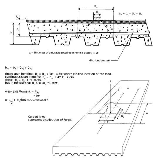
Untitled3_001_jxjkeo.jpg


for distribution of concentrated loads for deck slab design


Is it plausible to use the same for force distribution on the supporting beams?

Instead of image below
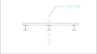
Untitled3_001_fctsez.jpg


Perhaps this could be used (image below)
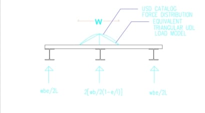
Untitled3_001_tfjo1c.jpg


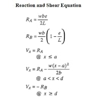
Reference for reaction calcs image below
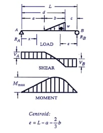
Untitled3_001_jnahbt.jpg

Untitled3_001_sgt9f5.jpg


Also could you refer to further calculation to incorporate the stiffness of the slab into spreading to adjacent supporting beams
in the scenario of concentrated load directly on top of the beam?
 
Replies continue below

Recommended for you

The load will take the stiffest path, which is likely to be the supporting beam directly below the load. By the time that beam were to deflect enough to engage the adjacent beams in any meaningful way, there would already be problems I'd bet.

You could look at the capability of the deck to span between the two adjacent beams pretending the beam directly below the load doesn't exist. If the slab has the capacity for that (which I doubt), then perhaps I could be persuaded. You could also look at the stiffness of the slab in that direction and do some deflection compatibility to determine how much of the load the slab can spread to the adjacent beams at some deflection and see how much load the beam directly below the point load can support at the same deflection. And see if those deflections converge to something reasonable when the combination of the two loads equals your total point load.

But I'm fairly certain even if you perform the above deflection compatibility analysis described above, you'll find the beam is so much stiffer than the slab, that the amount of load sharing is minimal and you'd have to reinforce/upgrade the beam. And if you're already upgrading the beam, might as well do it for the full point load amount.
 
If the concentrate load is directly on top of the beam, you should conservatively let the center beam (in this case) to take the entire load, then check the reaction of the slab using method of continuous beam with settled support.
 
thanks for your answers.. appreciate it

the entire scenario was not necessarily the beam max moment exceeding capacity with only that isolated point load
but with combination of multiple loads including this point load being directly over the beam causing max moment to exceed beam capacity

causing me to explore the options of potential distribution.

i had used finite element software which had given me results of approx. 20 60 20 for the load distribution

based on member sizes, slab thickness, etc ..


retired13 even if i calculated the deflection of the mid beam with total point load
and used deflection at that point for the support displacement with continuous beam with support settlement
how could this information help with reduction


Opposite to your thought, it is not reduction, as the beam takes 100% load, but the deflection will cause additional stress on the slabs. This approach is very conservative, obviously will not work for you. FEM is the way to go, if you modelled properly.

Actually, using the way I suggested can alleviate the load on the beam. The deflection will cause rotation at the adjacent beams, thus a portion of the load is carried over to each adjacent beam, the magnitude depends on the stiffness of the slab, and the adjacent beams. This method requires some iteration effort, thus not worth to recommended/get too deep into it. The result should be the same as those from the FEM though.
 
hi retired13
can you recommend any literature with this analysis?
 
The idea was based on beam on elastic support. I suggest to use the method sketched below to capture the effect of distribution due to support settlement and stiffness of the members.

image_pcomgn.png
 
The K in the sketch above is incorrect, please revise. Thanks.

image_su0lnm.png
 
There may be no bottom reinforcement at beam locations, so the notion that a portion of a load directly over a beam is transferred to adjacent beams is not recommended.

If the deck is composite, some bottom reinforcement may be present, but perhaps not on beams where the deck is spliced.

BA
 
The spring constant should be calculated using the wide flange beam under the concentrate load, and its span length. The strip width of the slab can either be "b[sub]e[/sub]", or "W", depending the direction of the panel, as shown on the sketch you provided.

image_kzy1pj.png
 
As pointed out by BA, after the analysis, you need to check the shear and moment capacity of the slab strip to resist the load. If there is any doubt, use FEM instead.
 
right but the beam is braced by the deck does that affect the stiffness?
 
No, the deck bracing the top of the beam just precludes buckling of the compression flange.

Does it act somewhat compositely? Probably yes to some degree, but it's hard to quantify when there is no idea of connection between the slab and the beam.
 
Yes. If this is a composite slab, then the spring will be much stiffer, as the deflection will be calculated on the composite property rather than the rigidity of the beam alone.
 
ooops i just deleted all my posts in thinking i misjudged that

because i had a low stiffness for the beam but i had a 12 multiplier in the formula somewhere =(

beam stiffness turns out to be about 170k
and slab stiffness 149k

i am getting a spread of 20 60 20 approx

using 2d analysis

which is consistent with the 3d model (slab width on 3d was 3.4ft where 2d model was 1ft)

however with 0.25 stiffness modifiers

spread is reduced to 17 66 17

i mean 34 percent reduction is not negligible
 
the deck is connected by self tapping screws
 
@wrxsti,

In future, kindly do not erase your post when someone has responded to it.

BA
 
I wouldn't consider the slab and beam composite. Not without shear studs directly connecting the slab to the beam.
 
Spring stiffness is variable depending upon location of the concentrated load on beam span. As spring stiffness increases, load sharing diminishes.

BA
 
Status
Not open for further replies.

Part and Inventory Search

Sponsor