Continue to Site

Eng-Tips is the largest engineering community on the Internet

Intelligent Work Forums for Engineering Professionals

  • Congratulations waross on being selected by the Eng-Tips community for having the most helpful posts in the forums last week. Way to Go!

Concentrated Load on continuous one way slab to supporting beams 4

Status
Not open for further replies.

wrxsti

Structural
Sep 18, 2020
196
hello i am trying to analyze concentrated load on decking to beam force transfer
in particular concentrated load directly over beam

in a previous post someone referred to image below
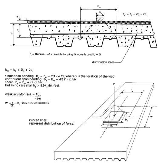
Untitled3_001_jxjkeo.jpg


for distribution of concentrated loads for deck slab design


Is it plausible to use the same for force distribution on the supporting beams?

Instead of image below
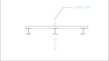
Untitled3_001_fctsez.jpg


Perhaps this could be used (image below)
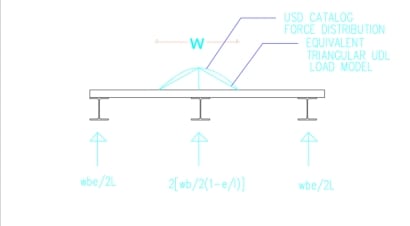
Untitled3_001_tfjo1c.jpg


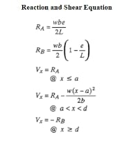
Reference for reaction calcs image below
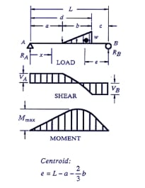
Untitled3_001_jnahbt.jpg

Untitled3_001_sgt9f5.jpg


Also could you refer to further calculation to incorporate the stiffness of the slab into spreading to adjacent supporting beams
in the scenario of concentrated load directly on top of the beam?
 
Replies continue below

Recommended for you

It could be a modeling issue. Double check your model, make sure torsional restrain is released. I wouldn't worry too much on a localized effect, which tends to smooth out, especially in concrete. But, no matter what, it is good practice to provide some additional bars at the corners.
 
Another modeling technic may help - make the mesh finer around concentrate load and sharp corners.
 
@retired13 when you say not worry do you mean neglect it and no extra reinformcement is needed there?
 
For good practice, I would provide add'l bars even without high stress. I will be concerned if it is high shear stress though.
 
wrxsti said:
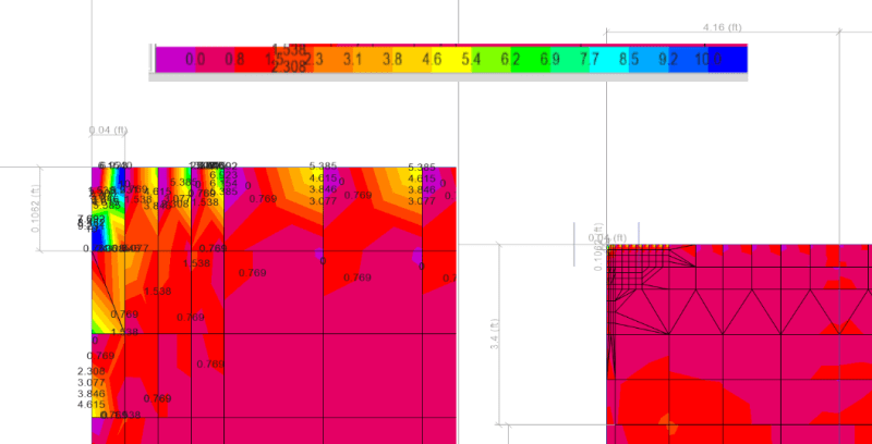
based on the fem model which i redid for the slab to cover entire bay
where in the load is distributed

The majority of slab is not overstressed

only the corners the stress values go up really high

this is NOT normal though right ?

Please excuse my ignorance, as I am not accustomed to interpreting this type of drawing. The surface has two colors, red and purple. The corners appear red, but so does a substantial part of the remainder of the floor. Does this mean the red area is highly stressed? If corner stresses are really high, shouldn't there be a different color to signify a trouble spot?

It is normal for corners of a rectangular area to be highly stressed. They are sometimes called "cornerlevers" because the corners are trying to lift up but are held down by their attachment to the supports. The code I used years ago required special reinforcement in the corners without precise analysis. The intent was simply to alleviate cracking in those areas.


BA
 
BA,

The color at the corners are darker, but as OP pointed out, it is about 1 sf, too small to be distinguishable on the PC monitor. We are on the same page as the corner bars goes :)
 
retired13,

I do see a black smear in each corner, but I thought that was just text printed very close together. I would have said the red color in the two corners is about the same shade as a fairly extensive section in the central area, but I can't claim to be an eagle eye, so I accept your assurances that the corners are darker.

BA
 
hey sorry got busy ok i increased the mesh maybe i need to do some more

here is the Mmax
Untitled11_001_ea4dva.png


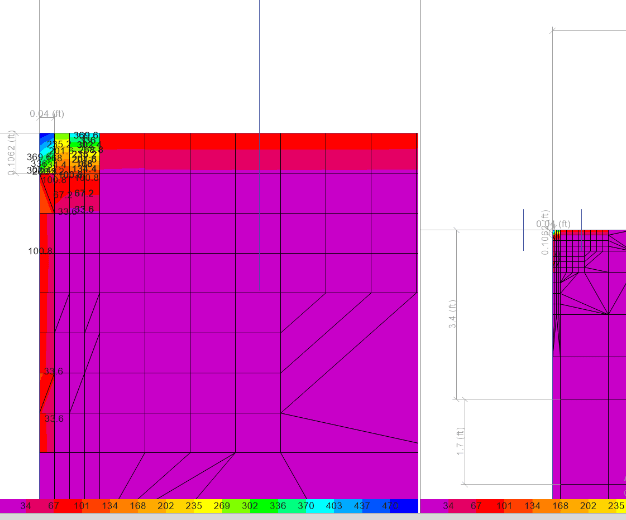
and here is the Vmax
Untitled12_001_dgyo3t.png


shear values going extremely high up to 398 kips

i will try with some end releases at the corner and post results
 
Check the model with self weight only, then add the concentrate load to see the changes. It might point out where the problem is - the model, or the load. If everything ends in no avail, try one run with a stiffer beam to see the improvement.
 
Status
Not open for further replies.

Part and Inventory Search

Sponsor