Continue to Site

Eng-Tips is the largest engineering community on the Internet

Intelligent Work Forums for Engineering Professionals

  • Congratulations KootK on being selected by the Eng-Tips community for having the most helpful posts in the forums last week. Way to Go!

Concentric holes - shifting datum MMC or LMC?

Status
Not open for further replies.

Th.Ro.

Mechanical
Apr 2, 2019
23
Problem:
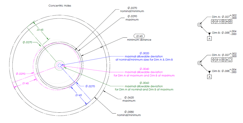
2 concentric holes that need to maintain a minimum distance between their walls.

If the larger hole, which provides the reference datum, is at its maximum tolerance the smaller hole can be more off its ideal position - see large view in below image.

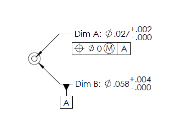
Which would be the correct drawing call-out for the datum shift, the upper one with MMC for the datum or the lower one with LMC for the datum?
Capture_kkydfh.png
 
Replies continue below

Recommended for you

Minimum distance between concentric hole surfaces where the larger one is the datum reference means that when the datum hole is the smallest (MMB) the considered hole should not violate the largest VC - zero tolerance is at LMC. So it's none of the 2 options you listed.
 
So this call-out without datum shift would cover the minimum distance requirement already?

Capture_2_evqzof.png
 
Is this what you understood from my response or are you simply asking a new question regardless of what I said?
 
I'm trying to find out what the correct call-out would be for the depicted range of allowances.
 
Not quite. Datum feature A should be specified at MMB, not LMB. Zero tolerance at LMC is correct. It will allow you maximum allowance while maintaining some value of wall distance that cannot be reduced and can only be enlarged.
 
Per what I remember from previous discussions does not matter if A(RMB) or A(MMB) in the FCF because the min-max distance between the walls are the same.
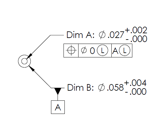
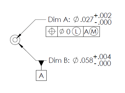
Otherwise stated position Ø zero at LMC |A| and position Ø zero LMC |A(M)| have identical results on the minimum and maximum results of the distance between the hole's walls.

 
greenimi,
It is true, but A at MMB will provide additional allowance while maintaining the same minimum wall distance.
The intended function will be achieved, with maximum flexibility for manufacturing. Obviously, the same minimum (at worst-case) wall distance can be achieved at RMB for the datum feature and RFS for the considered feature by modifying the diameter of the considered feature and the position tolerance value. The point of specifying material condition and material boundary modifiers is allowing more variation without detracting from the functional requirement.
 
Burunduk and all,

I agree what you are saying.
Now, the follow up question is: do you agree what 0.0145 is the minimum distance between the holes (as requested by the OP)?

I am talking about:
position Ø zero at LMC |A|
and
position Ø zero LMC |A(M)| cases.

Please let me know your thoughts.
 
Yes .0145 is the minimum distance in both cases. Note that if MMB is specified for A the maximum distance can be greater than in the RMB case.
 
Burunduk,
Burunduk said:
Note that if MMB is specified for A the maximum distance can be greater than in the RMB case.

Out of my curiosity what values did you get for maximum distances between those holes?
I got X maximum = 0.0195 for both cases (position Ø zero at LMC |A| and position Ø zero LMC |A(M)| cases. )


X maximum = .058/2 - .027/2+.004 (form error on datum feature A)

How did you calculate your X maximum? And why the values are different for X maximum?

Burunduk said:
Note that if MMB is specified for A the maximum distance can be greater than in the RMB case.

 
Maximum wall distance calculation for the LMC/RMB case:

Max. Wall Distance = A + y

Where:

A = Max. distance from datum hole A surface to LMC boundary of the smaller hole.

y = Max. distance from LMC boundary of the smaller hole to surface of the smaller hole.


A = (largest datum hole dia.* - LMC of smaller hole)/2 = (.062 - .029)/2 = .0165

(* Note: The LMC boundary is centered to the UAME of the datum hole. Any form variation of datum hole A will make the UAME smaller than the largest actual local size but it will not influence distance A. No actual local size may be larger than .062 therefore .062 diameter is used for the calculation.)


y = .029 - .027 = .002

Max. Wall Distance = A + y = .0165 + .002 = .0185

_________________________________________

Maximum wall distance calculation for the LMC/MMB case:

Max. Wall Distance = A + x + y

Where:
A = distance from the MMB boundary of the datum hole A to the LMC boundary of the smaller hole.

x = Max. distance from the surface of datum hole A to MMB boundary of hole A.

y = Max. distance from LMC boundary of the smaller hole to the surface of the smaller hole

A = (.058 - .029)/2 = .0145

x= .062 - .058 = .004

y = .029 - .027 = .002

Max. Wall Distance = A + x + y = .0145 + .004 +.002 =.0205
 
The question now is how to check this with a gauge if possible.
 
Since you are interested in maintaining the minimum distance you have the boundary for the larger hole - the datum feature simulator - outside the material, but the virtual condition boundary for the smaller hole is inside the material. That makes checking with a gage for the VC impossible.
 
Maximum wall distance for the LMC/RMB case will occur when:
The large hole is at its maximum size(Ø.062)
The small hole is at its minimum size(Ø.027)
Deviation of small hole's positionis maximum allowable

Burunduk said:
A = (largest datum hole dia.* - LMC of smaller hole)/2 = (.062 - .029)/2 = .0165

Based on the above understanding, I think the calculation need to edit as below:
A = (largest datum hole dia.* - LMCMMC of smaller hole)/2 = (.062 - .027)/2 = .0175

y = .029 - .027 = .002

.002 is the overall bonus, but it will only allow .001 radially away from the true position.
Hence, The max wall distance = A + y = .0175 + .001 = .0185

Althought the result is exactly the same, but the concept is different. Anyway, this is my thought, please correct me if I am wrong.

Season


Burunduk said:
Since you are interested in maintaining the minimum distance you have the boundary for the larger hole - the datum feature simulator - outside the material, but the virtual condition boundary for the smaller hole is inside the material. That makes checking with a gage for the VC impossible.

I was afraid this would be the case. So it got to be checked with an optical measurement system...
 
Status
Not open for further replies.

Part and Inventory Search

Sponsor