Continue to Site

Eng-Tips is the largest engineering community on the Internet

Intelligent Work Forums for Engineering Professionals

  • Congratulations KootK on being selected by the Eng-Tips community for having the most helpful posts in the forums last week. Way to Go!

Concentric Tubes in Bendine 2

Status
Not open for further replies.

toothless48

Mechanical
Oct 27, 2014
29
Hello all, I am analyzing a design that involves a stainless steel tube in bending. This tube is reinforced with a smaller "doubler tube" snugly fit inside (its OD being equal to the larger tube's ID). The tubes are not bonded, and are free to slide, ignoring friction. I have scoured the internet and my textbooks to no avail - how is the section modulus for this configuration calculated? The area moment of inertia of the cross section is the same regardless of the tubes being bonded or free to slide. I assumed, similar to composite beams, that two sliding tubes would be less stiff than one thick tube... Is this not true?

Many thanks
Mike
 
Replies continue below

Recommended for you

To clarify, I am trying to identify an effective single tube wall thickness to apply in an FEA model, to reduce complexity.
 
If you assume that there is no bond, and no other influence between the two tubes, then the share of the load to each would be simply based on their relative stiffnesses.

Since they are "with" each other in terms of deflection and share the same neutral axis, an equivalent shape would be a shape with the sum of the two moments of inertia...similar to two beams side-by-side but forced to deflect the same amount.

Check out Eng-Tips Forum's Policies here:
faq731-376
 
I might add that my qualifier here is important - that there is no influence between the two shapes. There is, however, got to be some influence since the inner tube will want to slide horizontally within the outer tube so some horizontal friction will in fact influence the two to some extent.

Check out Eng-Tips Forum's Policies here:
faq731-376
 
JAE,

Thanks for your reply. My hangup is this - a shape with an equivalent moment of inertia is just the same two tubes, considered as a solid cross section (unlike a stack of rectangular layers, where the MOI of the composite beam is larger than the sum of the layers). Is it possible that the tubes would not tend to slide under bending, meaning there would be no difference if they were bonded?
 
Assuming the inner tube freely slides inside the outer tube, the MOI is the algebraic sum of the two: I[sub]1[/sub] + I[sub]2[/sub]. For the combined sections (non-composite) use algebra to calculate the MOI of an equivalent tube with an outside diameter equal to the larger tube. With the same outside diameters, the elastic section modulus of the equivalent tube will be correct.
 
In reality, you've got to have some forces in between the tubes to transfer load from one to the other.
That being said, with the assumptions made in beam bending derivations, if the load is proportioned so that calculated deflection of both tubes is the same, there wouldn't be any sliding or shear between the two tubes.
 
In this scenario, bonding is irrelevant. The neutral axes of both the inner tube and outer tube coincide in space and will share the same curvature. As such:

1) The two sections will behave compositely in flexure in the sense that matters: they will share a common strain diagram.

2) The composite section properties will be identical to the non-composite section properties (I_in + I_out).

So there you have it. You get composite behavior but, in this particular case, it's of no particular benefit.

OP said:
how is the section modulus for this configuration calculated?

Assume that the section behaves compositely (or non-compositely as it's irrelevant here) and calculate S = (I_in + I_out) / c

OP said:
I assumed, similar to composite beams, that two sliding tubes would be less stiff than one thick tube... Is this not true?

No, that assumption is incorrect in this instance.

OP said:
To clarify, I am trying to identify an effective single tube wall thickness to apply in an FEA model, to reduce complexity.

You can simply add the two tube wall thicknesses for equivalent flexural properties.

OP said:
Is it possible that the tubes would not tend to slide under bending, meaning there would be no difference if they were bonded?

That is indeed correct and is probably the key thing to understand about this situation.

I like to debate structural engineering theory -- a lot. If I challenge you on something, know that I'm doing so because I respect your opinion enough to either change it or adopt it.
 
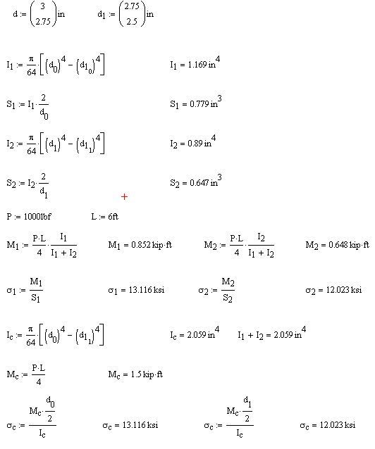
A little proof of what KootK is saying:

tubes_fce28p.jpg


The Mc is treating the tube as one, and looks at the stress at extreme fiber of the outer tube and extreme fiber of the inner tube. the results are the same whether you proportion the load by stiffness or treat it as a composite shape.
 
Thanks for the MathCAD confirmation SU10. But for laziness, I would have done that myself.

I like to debate structural engineering theory -- a lot. If I challenge you on something, know that I'm doing so because I respect your opinion enough to either change it or adopt it.
 
but is that the way the inner tube would work ?

you may have a point load on the outer tube, but the inner tube would load up from a non-uniform distributed load (as the outer tube bears against the inner).

my sense says that the two tubes should be less stiff and a single tube, because you have a shear slip boundary between the tubes.

another day in paradise, or is paradise one day closer ?
 
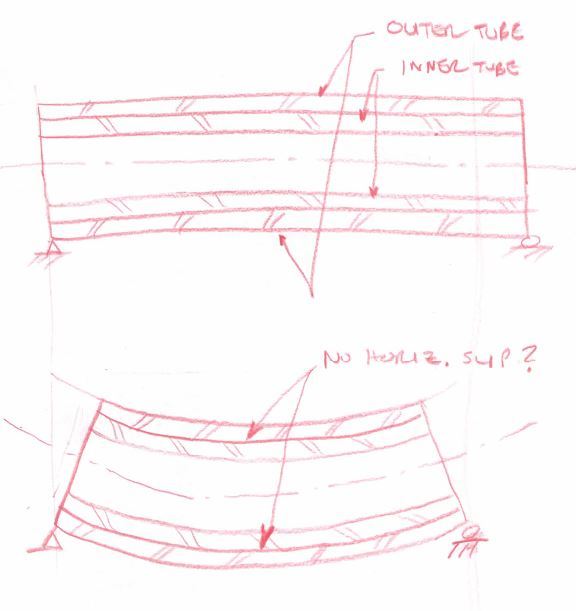
not so sure about this......effective composite action requires horiz shear capacity between the the 2 tubes...if the assumption is that this capacity does not exist, then , I would check it in the following manner....
1. Check the same two tubes independetly....assume an equal(same) deflection for each and find it's
corresponding applied load. Add the 2 loads to get total load.
2. Check the capacity for the same defection of an equivalent tube with a total I equal to the sum
I1 & I2 and with an OD of the larger tube and wall t equal to t1 + t2...
3. Compare the loads of method 1 with method 2....
 
Junk_xuva1p.jpg


Check out Eng-Tips Forum's Policies here:
faq731-376
 
if the inner tube was an interference fit, then I'd by that the pair of tubes would act like one combined tube (or like the sum of the Is, same diff)

as a sliding fit, there is an obvious difference and the interface of the tubes between the two tubes and a single thick tube. I'd expect the two tubes would deflect more than a single thick tube.

another day in paradise, or is paradise one day closer ?
 
Exactly right. No slip so long as:

1) The vertical positions of the neutral axes for both members are coincident and;

2) The neutral axes of both members are made to have matching curvatures.

1 + 2 = identical strain profiles for both members at all locations. And identical strain profiles, by definition, means no slip.

rb1957 said:
I'd expect the two tubes would deflect more than a single thick tube.

I feel that structSU10 pretty convincingly demonstrated that I_composite = I_non-composite. Do you dispute that? If not, why would you think the composite section to be any stiffer?

I like to debate structural engineering theory -- a lot. If I challenge you on something, know that I'm doing so because I respect your opinion enough to either change it or adopt it.
 
"Do you dispute that?" no, the math is straight forward; but will be beam behave that way is a different question.

do you see a different if the inner tube is interference fit ?

in the single thick tube, is there no stress on the parting plane ? (I don't think so, but there is in the two tube case)

in the two tubes, a single point load on the outer tube would not load the inner tube as a point load (IMHO) but the inner tube would be loaded (and the outer tube relieved) by a distributed load (as the outer tube bears against the inner one).

I'd analyze as the outer tube loaded by the point load, reacted by a distributed load and end reactions. At the same time the inner tube is loaded by the distributed load. now calc deflected shapes and tune the distributed load so that deflections of the two are the same.

another day in paradise, or is paradise one day closer ?
 
rb1957 - the loading isn't really relevant here because the physical conditions force both tubes to deflect the same distance, and with the same curvature.
Force follows deflection and visa-versa. Hooke's Law.

No matter how they are loaded, the two tubes are deflecting in the same curve/pattern/degree and so they would indeed (as KootK mentioned) share the same strain diagram.

Check out Eng-Tips Forum's Policies here:
faq731-376
 
this is a slip fit to begin with....if the assumption is that there is no effective means of transferring horiz shear between the 2 tubes, it then poses the question why ,in this application, is it necessary at all....one could apply this reasoning to a laminated wood beam and assume that the bonding between layers as being unnecessary...
I have not run the numbers, but my intuition tells me that the stiffeness of the 2 tubes would be approx 75% of that of an equivalent tube as described in the previous posts...then , again, I would not bet my shirt on it....
 
Status
Not open for further replies.

Part and Inventory Search

Sponsor