Continue to Site

Eng-Tips is the largest engineering community on the Internet

Intelligent Work Forums for Engineering Professionals

  • Congratulations cowski on being selected by the Eng-Tips community for having the most helpful posts in the forums last week. Way to Go!

Conceptual question on reinforced concrete design

Status
Not open for further replies.

fa2070

Structural
Jun 6, 2007
58
Hi,

This is a conceptual question on reinforced concrete design.
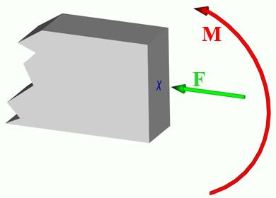
Given an arbitrary cross section subjected to a normal force F and a bending moment M (see picture), how do I tackle its design? Is it a beam with a normal force or is it a column with a bending moment? How do I tell?

Section.jpg


Thanks.
 
Replies continue below

Recommended for you

Depends on the amount of axial load compared to column capacity.

Code gives a limit on when it needs to be treated as a column.
 
Yes, we all know the 5 age-old strain zones and the frontiers between strains in concrete and steel, etc. that we all learned in college.
Leaving codes aside, and applying pure common sense together with the necessary backing math, how do I tell if I have to apply the nomograms for columns or the graphs/tables for beams ?

Thanks.
 
I think if you leave the code out of it and attack it from a mechanics point of view, you should get the same answer either way.
I'm not sure exactly what charts you're talking about, but they likely have the appropriate phi factors embedded in them so you ARE still applying the code.
ACI doesn't really recognize beams or columns, it is more a matter or tension-controlled, compression-controlled, or transition.
Finally, when talking about a cross-section and not a member there is only a strength consideration since buckling can't be considered for a given cross-section without analyzing it on a member level.
 
A column interaction diagram takes into account the transition from column to beam. The closer you get to zero axial load the larger phi gets until it reaches 0.9.

Why would you not want to consider this? If you are trying to ingnore compression reinforcing then you really need to treat it as a beam and superimpose the compressive stresses over the bending stresses.
 
Why does it matter if it's a "column" or a "beam" it's a cross section with an load applied eccentrically.

To quickly check the "interaction" is done quite easily in excel or mathcad... or if you conservatively ignore compression steel it can be solved by hand if you assume tension steel yields... which it most always will... then you can back our your phi factors.
 
Thanks all who responded.
I just wanted some clarifications, as more often than not codes tend to overshadow the fundamentals of reinforced concrete with design constraints that many engineers follow blindly without putting the things in the right context.
 
Generally speaking, I tend to ignore compressive loads if they are less 30% of Pu, becuase from the interaction diagrams compressive loads only add to you're bending capacities if your axial load is that small. In such cases I just calculate phi*Mn (phi=0.9) and call it a day.
 
If the tension is less than the modulus of rupture, the beam behaves elastically. It is like a prestressed or post-tensioned beam.
 
NS4U has made good advice, 30% seems a reasonable limit as long as the member is not really slender.
 
No matter it is called beam or column, when a member subjects to both axial forces and bending memonts, the design needs to ensure the member is capable of carrying both. Keep in mind that a column will buckle, a CIP floor beam deflects but not likely to buckle. Also, the axial compressive force will indeed increase the moment in the column if eccentrically loaded, however, the same force may increase or decrease the stresses in a beam, depending on location of the load center with respect to geometry center (prestress, sounds familiar?), and the stage for which the axial force is introduced (before/after the member has deformed/deflected).
 
kslee1000-

How would the order in which (I'm assuming that's what you meant) loads are applied matter?

Even if you apply an axial force first, then apply a load perpendicular to the cross section, the p-delta effect will be exactly the same.
 
frv:

It's rare event, you are thinking the applied load in direction of the gravity, mine is in reverse.
 
That still doesn't explain how it would make a lick of difference which load is applied first.
 
frv:

Try the excerise at home:

Case I - plate subjects to uniform selfweight only with axial load (W+F+M). Then add equal upward pressure (-U).
Case II - plate subjects to uniform selfweight and equal upward pressure (W+(-U)). Then add axial load.

Draw stress diagrams to see the differences.
Hint: For case I, there is lock-in stress due to selfweight (permenent deflection), whereas, case II has none since W=U in magnitude.
 
kslee1000-

In a 2nd order analysis, you are right- it would change the stress distribution.

It must be said, however, that your scenario is terribly improbable and has no bearing on an actual analysis problem.

From a practical standpoint, your second scenario is most likely trivially advantageous (how much so depends on several factors including the magnitudes of the loads and the flexibility of the member), although I can't imagine how you can possibly design for such a specific scenario. You always design for a worst case.

But I'll cede the conceptual point.
 
frv:

There are quite a few real word cases if you deal with fluids. That 2 cases were specifically constructed for ease of visualizing the effect of loading sequence on internal stresses. Try think deeper before reject.
 
kslee1000-

I'll ignore the patronizing tone for now.

This is a structural engineering forum. Yes- structural engineering covers a wide array of structures. However, unless specifically stated otherwise, one assumes buildings and "building-like" structures when forming opinions on the subjects covered in this forum.

Admittedly, I am ignorant as to the specifics of design of structures like vessels or containers or whatever else you have in mind when you are saying there are "quite a few" real world scenarios where uplift exactly equals gravity loads.

The principles certainly are the same, but the practical, experience-related aspects of design can differ greatly.

For example, it is obvious that in your line of work this may be an important consideration, but I have never (which doesn't mean much due to limited experience), nor do I know of anybody who has ever (which means a lot more, as I've worked with engineers with decades of experience) had to design any member differently due to the "sequence" in which the loads are applied.
 
To me, it looks like a simple centerline Prestress beam analysis. Simple.

Mike McCann
MMC Engineering
 
Status
Not open for further replies.

Part and Inventory Search

Sponsor