Continue to Site

Eng-Tips is the largest engineering community on the Internet

Intelligent Work Forums for Engineering Professionals

  • Congratulations waross on being selected by the Eng-Tips community for having the most helpful posts in the forums last week. Way to Go!

Concrete Pier Foundation Cracking 5

Status
Not open for further replies.

acer49

Structural
Jan 28, 2013
17
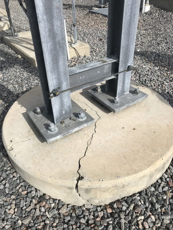
What can cause this type of cracking? My first guess is lack of adequate shear reinforcement or some eccentric loading based on the anchor bolt/column configuration. The piers were constructed in 2009 and designed by someone else. Piers are 5'-0" in diameter with #4 ties at 12" O.C. vertical reinforcement is (8) #7 rebar equally spaced.

Also, have no concrete pour data, break reports, foundation specifications, or soil data available.
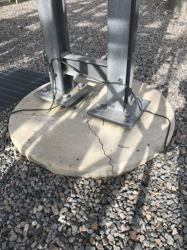
Pier_2_-_1_rpq5eh.jpg
Pier_2_-_4_edpvcq.jpg
 
Replies continue below

Recommended for you

bones206 said:
I’ll give it a shot. working off my phone so bear with me.

α = 0.0000072
ΔT = 55 F
Say A = 4.43 in2 (W6X15)
E = 29,000,000 psi

Full axial restraint —> PL/AE = αΔTL
P = αΔTAE = axial force in cross member
P = (0.0000072)(55)(4.43)(29,000,000)
P = 50,874 lbs

The actual force would be relieved somewhat by the outward bending of the posts.

Not to nitpick, but area suddenly appears in the above set of equations. Was the cross member size revealed somewhere?

It also interesting that almost every picture has the cracks bisecting the pier between the two columns. The only picture where the crack doesn't run between the two columns is the first picture of the second set of photos. Here the crack runs under the columns in-between the 4 column anchors.

I wouldn't think it would be any type of shear failure as well, as the beam just above the base plates would virtually connect the two column bases together, that is, if one set of anchors started to fail in shear then the beam would "drag" that shear to the other set of anchors.

Definitely an interesting problem. How would you ever accommodate thermal expansion in a similar system while preventing the columns falling over in all directions?
 

I was just assuming a member size. I think someone had mentioned it looked like a W6X15 so I just went with that.
 
Columns are W6x20 and the cross member is W6x9.

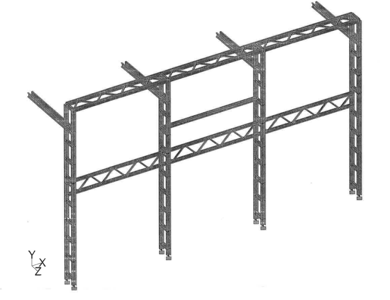
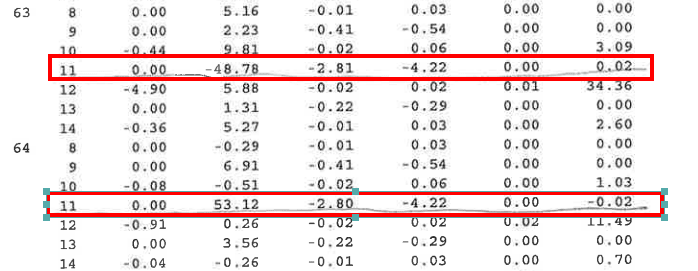
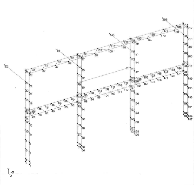
Here is the 3D model of the structure and still waiting on site photos. Also, here are the reactions Nodes 63 and 64 would be the (2) columns on the the (1) pier foundation.

Don't know if the hoops are lapped correctly. Scheduling a site visit to collect information soon.

Capture_nqq5fj.png

aa_vvrue9.png
 
The huge Mz in LC12 is intriguing. Do you know what is the load case?
 
Extreme Wind in the X direction is LC12.

The headers for the reactions in this order: Joint, LC, FX, FY, RZ, MOM-X, MOM-Y, MOM-Z
 
Jt 63 has a negative Fy (-48.78) while Jt 64 has a positive Fy (53.12) What is causing a couple of that magnitude about the X? At the same time, the MXs are identical.

Since you have short beams connecting the columns periodically spaced, that somewhat rules out the fulcrum concept.
 
Are reactions from wind in Z-dir included in the output?
 
@retired13, yes the reactions from wind in Z-dir is included. That would be load case 11
 
The wind load in the Z direction and there are concentrated loads in the Z direction as well. This is some sort of cantilevered steel structure.
 
Can you label jt63 & jt64 on the 3D model? I guess each is at the base of column in the built-up structure. If so, the large +Fy/-Fy make sense. Please verify, thanks.
 
Now I think someone here should be able to assess the crack mechanism due to the following conditions:

1) Two columns share same foundation with reversible loads due to wind in opposite directions over 10 years (±Fy on joints 63 & 64).
2) Reversible Mz caused by wind in X-direction over time.

Any comment?
 
There is a macabre joke hiding in this thread about Accelerated Pier Construction, but I'm not going to make that joke.

==========
"Is it the only lesson of history that mankind is unteachable?"
--Winston S. Churchill
 
I've noticed exterior guardrails in cold climates with a horizontal rail within a few inches of the support. This could likely cause a similar effect, but, I've not noticed any distress.

Dik
 
Would that be fatigue has getting into play after cyclic loading reversals occurred over a lengthy period of time? I am particularly concerned with the rocking phenomenon in the Z direction (sway about X axis), albeit the wind load does not seen too excessive.
 
bones... thanks for the info. Now to decide to adopt this into my railing details... since it's not done that I'm aware of.

Dik
 
Status
Not open for further replies.

Part and Inventory Search

Sponsor