Continue to Site

Eng-Tips is the largest engineering community on the Internet

Intelligent Work Forums for Engineering Professionals

  • Congratulations waross on being selected by the Eng-Tips community for having the most helpful posts in the forums last week. Way to Go!

Concrete Shear Wall Stiffness Adjustment Factor – Iteration Process Discussion 11

Status
Not open for further replies.

polskadan

Structural
Nov 8, 2011
21
US

Hi all, I wanted to inquire about how some of you perform your iterative design process for concrete shear wall crack factors and also discuss my current methodology. I am hopeful that I may be able to create a more efficient process and try to hone down on what may be considered more of a standard “industry practice.” Please note that for this discussion I am discussing the stiffness factors for concrete walls used for design under factored load combinations (not serviceability) as per ACI 318-14 sec 6.6.3.1.1a. Also note that seismic does not control therefore this discussion will strictly pertain to wind loading and linear, pre-yield behavior of the structure.

Scenario: 20 story concrete structure with (3) shear wall “groups” that make up a “shear core.” Each shear wall group consist of (4) walls that form a rectangular shape.

Iteration 1: My first iteration is performed with all walls uncracked using .70Ig -> plot results -> All walls that are ‘cracked’ have their respective cracked factors modified to .35Ig to represent Iteration 1 results (This is done at a per level, per wall basis).
Iteration 2: Using the updated wall crack factors from Iteration 1, I perform a 2nd iteration of the model with crack factors of .35Ig on walls that cracked in Iteration 1, and .70Ig for uncracked walls -> plot results -> Walls whose status match their crack factor remain as is (cracked stays cracked, uncracked stays uncracked, remaining walls have their factors adjusted to match iteration 2 results.
Iteration 3 & beyond: Continue to adjust factors as discussed in iteration 2 until all values converge
At this point I should clarify that the ultimate goal is to have all cracked factors for each individual wall segment at each floor converge with the input factor when checked for all load combinations. This means that if a wall is shown to crack in any of the checked load combinations, then this wall shall have an input of .35Ig and vice versa if the wall is shown to remain uncracked when checking all load combinations, this wall will have a .70Ig.

The issue that I come upon is that I end up chasing my tail when limiting myself to only .35/.70Ig. As you change the stiffness of individual wall groups, you are modifying that load path and subsequently distributing more load to adjacent wall panels. By limiting myself to .35/.70 it seems as if I am trying to say everything is either “white or black” and ultimately consecutive iterations are mere inverses of the previous results. It would appear that in order to accurately reflect conditions, I would need to find “effective” moment of inertia’s for each respective walls segment, but this would be a very time consuming process when one is forced to do this by ‘hand.’ This need for an effective stiffness becomes apparent when one sees the results constantly inversing between 2 sets of walls flashing between “cracked and uncracked” when in reality the wall groups share this load and are somewhere in between.

I have heard from a colleague that "once a wall cracks it is cracked." This is an obvious statement, however it is a more complex issue when we as the engineers are telling the programs which walls are cracked/uncracked and subsequently manipulating where the load is to go. I am under the belief that in a perfect world I would create effective moments of inertia for each individual wall segment (per floor), however I am curious to see how far other engineers/companies take this design approach to get a stiffness model that accurately represents the intent.

I am also curious to find if I am overthinking this and if the general engineering community uses a cracked factor of 0.5Ig for all entities as allowed in ACI 318-14 Section 6.6.3.1.2 😊.


Replies continue below

Recommended for you

As you have noticed already, using the iteration method is not very practical, we did the old ways - envelop the results from all cases.
 
What analysis program are you using? This seems ripe for a non-linear type of analysis if your program can handle it.

Not sure how I would handle setting up the elements, but I am sure we could figure something out if you are using ETABs or SAP.


S&T
 
I am using RAM Structural system. I believe that this software is commonly used in our industry and was hoping to get input on how others typically approach the 'iterative' portion of their design with similar software. Having (2) models, one with cracked walls and the second model with uncracked walls, and designing for both extremes (envelope solution) is certainly one approach, however I have a hard time believing that most engineers currently use this method.
 
OP said:
however I have a hard time believing that most engineers currently use this method.
Why do you say that? To me that's much simpler than running the model multiple times iteratively over and over. Only to, at times, find out that the majority (if not all) of the walls do end up in a cracked state.

I'd rather build one model (either cracked or uncracked), then save a second model and adjust the stiffness accordingly to the other option. Then I've only got to run two analyses. Grab the maximum results from each run and design each element only once.

That being said, I practice in a non-seismic location and therefore don't need to account for hinging, energy dissipation or anything like that.
 
jayrod12 said:
Why do you say that?

I honestly do not have much to base my opinion off of besides more recent structural literature that discusses iterative approaches such as this one:

[URL unfurl="true"]https://www.structuremag.org/?p=10924[/url]

With discussions in our community regarding 'iterative' processes along with the development of structural analysis software, one can only guess if other engineers have created their own processes to replicate the iterative procedure or if most are sticking with the old school envelope procedure. It would be nice to receive input and see if other engineers on this forum also have stuck with the envelope solution.
 
Polskadan -

Thank you for posting. I believe your question is a very good one that not very many engineers are putting much thought into. I'll have a slightly different perspective coming from more of a software background (I've worked for both RISA and CSI in my career).

My thoughts on this are the following:
1) First we need to acknowledge and understand that we are only estimating an elastic stiffness for these walls. The goal is to come up with a reasonable stiffness for our analysis and our design. We know 100% that these walls do NOT behave elastically.

2) 0.70Ig isn't really an "uncracked" wall. I know that's what the code says. But, I think of it more as a "normal" level of cracking for a compression member. You'll have temp / shrinkage cracks and such. But, you won't have the major flexural cracks that result from the flexural tension stresses exceeding the axial compression stresses.

3) I agree that the "black / white" designation of "cracked/uncracked" is problematic. Such a dramatic stiffness change can cause iteration / convergence issues. What we would really like to see is a "transitional" stiffness between 0.70 and 0.35 times Igross. Right?

4) Table 6.6.3.1.1(b) does a okay job of this.... transitioning between 0.875*Ig and 0.35*Ig. So, you could use that formula to do the transition manually. Though, ideally, you would have a program do this (or something like it) for you automatically.

5) To some extent, I think we can lose track of the goal. We're not looking for a perfect analysis. Any elastic analysis is going to be imperfect. We just want to be reasonable with the stiffness we're using. In that respect, I would probably advocate for a simpler formula than given in 6.6.3.1.1b if I were doing this my self something like adjustment factor = 0.70*I*(Pu/A - M/S) where A and S are based on gross properties. And, you limit this to a maximum of 0.70 and a minimum of 0.35.

Again, I'm not trying to be perfectly accurate. I'm just trying to come up with something halfway reasonable. No matter what, I would probably stop after two iterations.
 
OP said:
I believe that this software is commonly used in our industry and was hoping to get input on how others typically approach the 'iterative' portion of their design with similar software. Having (2) models, one with cracked walls and the second model with uncracked walls, and designing for both extremes (envelope solution) is certainly one approach, however I have a hard time believing that most engineers currently use this method.

For serious high rise buildings in competitive high-rise markets, you'd better believe that engineers are are iterating to get favorable results rather than just bracketing the the extreme solutions. That, in combination with all of the extra complexity that comes along with introduction composite shear wall coupling beams etc which have their own issues with respect to accurate modelling. This will have an enormous impact on the building wind design for occupant comfort and high dollar ULS items like hold down, tension pile demands. And then there's seismic...

Most everybody acknowledges that all of this stuff is pretty serious BS with respect to accuracy and predictive value. In my mind, what really need to happen with this is for some jurisdictional body to set out clear guidelines for what the modelling rules will be going forward for everybody. The key is to set a level playing field for this so that it is not so heavily dependent on designer/firm judgment. That system winds up just being a race to the bottom design wise.

To this day, I don't believe that there are even clear guidelines establishing what slab widths one should use for an equivalent frame, slab-frame lateral system where those can be used. And I know for a fact that there are designers out there using all of the slab width for this purpose. And slab torsion too! Why not? Better answers, happier clients, no consequences. Where nobody minds the store, it gets jacked. No big surprise there.
 
I've a little different take on this - when I feel the necessity to perform iteration, the goal is to identify the weakness that may not be uncovered through simply envelop the extremes. Do we really want the code to mandate the design/analysis approaches that everybody shall follow and be doing the same, I doubt. If it is going to be the trend, for an extreme, the code body no longer needs to issue/update codes, but to write programs instead. Please note the difference between code suggest/recommend methods, and the codified solutions. I welcome the former, but don't wish to see the latter. Sorry, don't mean to dispute, just let my feeling out.
 
KootK, I'm going to disagree with you. That's seems like it kills innovation. Why should a firm be penalised if they can demonstrate they are pushing the boundaries of structural engineering, knowledge, research and application of codes/design guides. This is all assuming they are doing this innovative work based on sound engineering principles and the latest research.

I've had a look into this very problem several times over the past few years and it's not straightforward. Applying general stiffness modifiers, smearing them across various walls and iterating the whole process is like setting the FEA mesh size to 10 metres. Rarely worth the effort for the accuracy it spits out.

Shall we talk about non-linear layered shells with x% vertical and horizontal reinforcement now?

 
Trenno said:
That's seems like it kills innovation.

I can only speak from the perspective of my own personal experience on this. To date, I've worked at three big high-rise firms and have been involved in peer reviews with four others, including yours. From what I've seen, "innovation" at the skyscraper firms mostly means:

1) Digesting the same, very shallow pool of literature and resources available to us all.

2) Interpreting #1 in the boldest, most liberal manner conceivable.

3) Stuffing #2 into ETABS, PERFORM 3D, or whatever the latest fad is and aggressively marketing the results as boundary pushing innovation that only the insiders are capable of.

4) Sometimes pairing these NASA level analyses with fundamental detailing errors that any decent, 3rd year EIT would be ashamed of.

As far as I can tell, the only difference between a senior engineer at Thornton Tomasetti and the analogous guy at Mike's Beams-R-Us is that the TT guy has the confidence that comes from knowing that, even though he's scared witless about the design assumptions that he's making on his 90 story building, the guy in the cube next door made the same assumptions on an 88 story building last year and lived to tell the story.

The one exception that I'll allow for, and I'm sure that there are others of which I am unaware, is Magnusson Klemencic Associates. Via their partnership with the Charles Pankow Foundation and the west coast universities, they really do seem to be pushing the body of knowledge forward in a meaningful, non-BS way. And I'd not begrudge them the creative use of the technologies that they themselves have helped to develop.

Trenno said:
Why should a firm be penalised...

I don't see it as anyone being "penalized". Rather, I see it as the leveling of the playing field and the cessation of reward in exchange for excessive risk taking. This question gets asked here constantly. And nobody ever has a definitive answer to offer up. If the answers on this are buried so deeply that nobody here knows of them, and you've got to be a member of the Priory of Sion to gain access, should anybody really be making use of such information? It's civil engineering for Pete's sake. It's kind of meant to be public domain stuff. It's not like we're developing secret space lasers etc.

Trenno said:
Shall we talk about non-linear layered shells with x% vertical and horizontal reinforcement now?
.

By all means, please enlighten us and tell us how to do this the right way. I, for one, would absolutely love to finally know.

Let me guess... it's proprietary and would compromise your firm's competitive advantage?
 
KootK -

Tell us what you really think. Don't sugar coat it this time! LOL

In all seriousness, some quick comments (some of which agree with your post, some of which do not):
4) Sometimes pairing these NASA level analyses with fundamental detailing errors that any decent, 3rd year EIT would be ashamed of.
This (IMHO) is an excellent point. One that everyone should pay attention to. What good is a 5% reduction in force from your analysis if you screw up the construction documents with bad detailing?! To me this is what separates people like me (i.e. the FEM jockeys of the world) from the really good engineers. The really good engineers know how to put a set of drawings together and and sniff out bad detailing like a blood hound.

Stuffing #2 into ETABS, PERFORM 3D, or whatever the latest fad is and aggressively marketing the results as boundary pushing innovation that only the insiders are capable of.
Just to be clear, if you're talking about Perform3D then you're talking about doing a non-linear analysis. This is very different than the subject of this thread.... which deals with assumptions about the LINEAR stiffness used for shear wall analysis. Hence, it may be an unfair comment / criticism.... at least for this thread.

Caveat: I work for the company that writes ETABS and Perform3D.
 
I am also curious about how to set nonlinear material (concrete) properties into the program. Any commercial program package does that? Otherwise, seems it will loop back to the dilemma of 0.7Ig, or 0.35Ig.
 
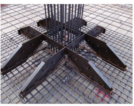
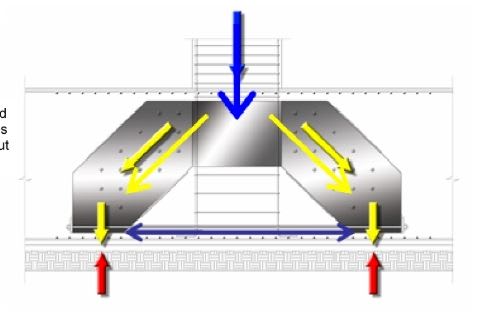
To attempt to put my money where my mouth is, here's one of the big innovations from a NY highrise firm. Apparently, these magical, STM, punching shear preventers have been installed at the base of some Manhattan Skyscrapers. All the FEM'in in the world won't be worth squat when the columns just slide through the hole in the middle. What do I know though? I'm just some internet nutball lacking a back stage pass to Club Skyscraper

C01_y2qcjc.jpg


c02_bldrm9.jpg
 
JP said:
Just to be clear, if you're talking about Perform3D then you're talking about doing a non-linear analysis.

Oh, I know. My beef is not with the software or the software vendors. They simply supply that for which there is burgeoning demand.

JP said:
This is very different than the subject of this thread.... which deals with assumptions about the LINEAR stiffness used for shear wall analysis. Hence, it may be an unfair comment / criticism.... at least for this thread.

Pffft... fair schmair.

1) So I've moved the needle in this thread a little. OP will live.

2) I really take OP's fundamental question to be "How the hell are we all, as a community, designing our cracked core walls?". In this context, all methodologies are on the table for discussion and the overarching truth of things is more important than the particulars.
 
retired13 said:
Otherwise, seems it will loop back to the dilemma of 0.7Ig, or 0.35Ig.

That's exactly right. I can't find it now but somebody in my LinkedIn network is a purveyor of an ETABs post processor that will analyze your ETABS shear wall stresses, crack your wall elements accordingly one by one, and then feed those values back into the ETABS model as adjusted input. All fine and dandy if you don't mind ignoring the effect of reinforcement in your concrete.

 
retired13 said:
I am also curious about how to set nonlinear material (concrete) properties into the program. Any commercial program package does that? Otherwise, seems it will loop back to the dilemma of 0.7Ig, or 0.35Ig.

In order to get the juices flowing here... I'll take the first stab of how I would do it in ETABs/SAP.

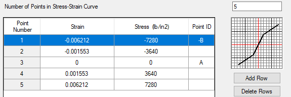
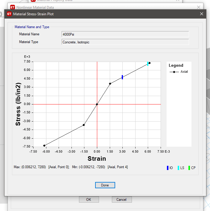
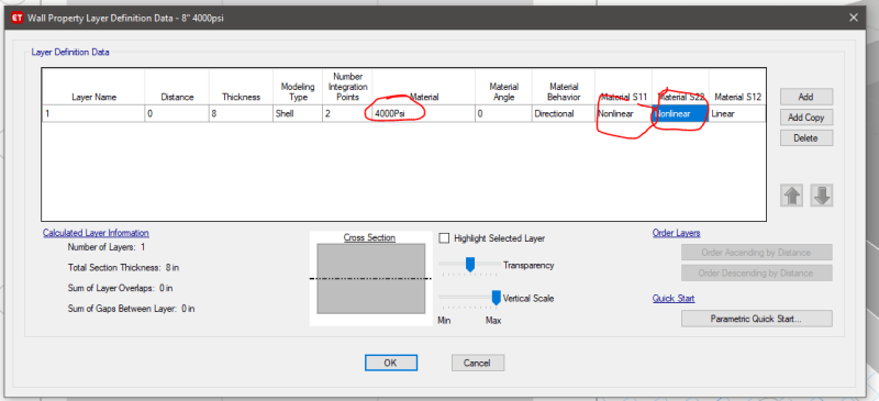
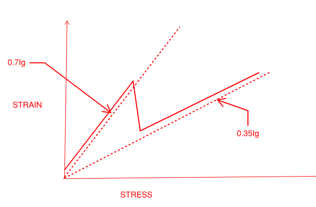
Set nonlinear material stress-strain plot that is somewhat binary in nature. Up to a certain stress level you have a certain E (representing the 0.7Ig region) after that, cut your stress-strain slope in half (representing 0.35Ig region). Images shown below, i have not done the research on what these values are, just shown for example


image_qlz9mz.png

image_zwwhfw.png


After that, setup a layered shell in ETABs with non-linear nature in the S11 and S22 direction.

image_g0jusd.png


Note, I have no idea if this is the correct way to handle this, but those are my thoughts. I can run some test models for the group and post results if interested.

I am sure Josh might have some good pointers for us as he works for the company.


S&T
 
Stress strain curve for the concrete? I need time to digest, thanks anyway :)
 
Actually now that I thought about it a little more, maybe the stress strain curve would look something more like this
(sorry i flipped stress and strain on the diagram, you should get the picture though)
image_v0oryd.png


S&T
 
JP said:
Caveat: I work for the company that writes ETABS and Perform3D.

Now I can't resist and am curious to know what you think of this...

I've always attributed the meteoric rise of CSI primarily to the innovation that is ETABS. In particular:

1) Early anticipation of, and catering to, the structural engineering community's desperate wish for the ability to handle gravity & lateral design in a single, 3D model and;

2) Not explicitly telling designers how building lateral design ought to be undertaken while simultaneously providing convenient tools for designers to do what their instincts will lead them to want to do naturally.

3) Staying the hell away from light frame construction where the value proposition is much lower while the programming is probably actually trickier.

Marketing & strategy genius it is/was.

 
Status
Not open for further replies.

Part and Inventory Search

Sponsor

Top