Continue to Site

Eng-Tips is the largest engineering community on the Internet

Intelligent Work Forums for Engineering Professionals

  • Congratulations cowski on being selected by the Eng-Tips community for having the most helpful posts in the forums last week. Way to Go!

Confusion over Datum choice on Positional Tol. 2

Status
Not open for further replies.

R1chJC

Marine/Ocean
Apr 15, 2015
51
Hi All,

Perhaps people can help me with a debate we are having at work.

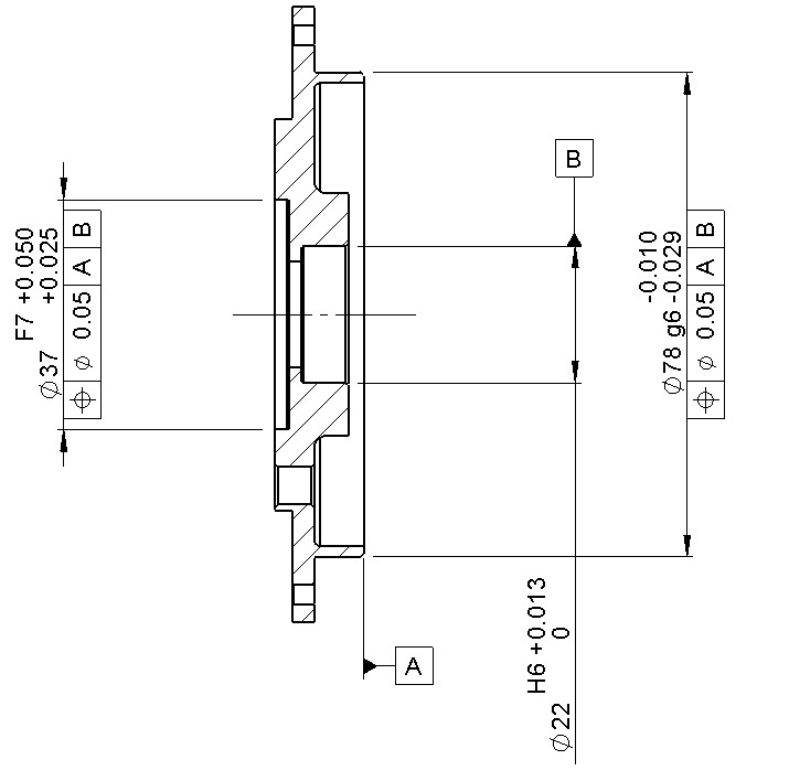
See picture.

My colleagues are questioning what Datum A brings to the table for the positional call-out on the ∅37. They argue that referencing Datum B should suffice for controlling the concentric relationship between the two bores.
From a functional perspective, the Datum B bore houses one end of a shaft bearing. The datum A face is a spigot/location diameter that abuts to a mating part in the main housing. I want to ensure all bores are concentric. I'm also trying to convince them that using an actual concentric tolerance is not necessary and inspecting it is pure evil..

I thought that having datum A introduces a perpendicularity control. A separate thread here: Link describes something similar and I can follow the train of thought in that post, but i'm having a hard time applying that logic to my example.

I've seen it many times where a positional tolerance for a bore references a perpendicular mating flange face.

We work to ASME.

Thanks all.
Tol_Example_ba03sv.jpg
 
Replies continue below

Recommended for you

R1chJC said:
The more I read about GD&T the less I think i understand....

Do not be frustrated. Your OP is the MAIN purpose of GD&T: to force you to think and understand how parts "function and fit-up" and then use the symbols to communicate the concept the best you can. After 35 years I still "fight" to applying the controls, hoping the interpretation will be as I intended.

Keep at it. Don't work in a vacuum, use the Forum to expand your understanding.


Certified Sr. GD&T Professional
 
What can help is to build exaggerated models/views with compliant deformations that are clearly visible.

Another aid is to build a directed graph that has each surface of the part joined by the applied tolerances. This can be applied to the entire assembly, but need not include surfaces that will not participate. With the graph done, you can look at the tolerance path between surfaces that don't have explicit applied tolerances.

In the first image one would immediately notice that there is no relation between A and B, so there isn't a way to know how much variation in the orientation of A with respect to B is acceptable.
 
R1chJC,
With regard to the question: "What would be the effect of removing datum A altogether and just referencing Datum B for positional?", I think that attached graphic may help you a little bit to understand the effect of removing A from the positional callout applied to dia. 37 cylinder.

This (especially the picture on the right) and the fact that the part is clamped to the housing should also slightly help you to find an answer to the question whether functionally dia. 23 bore is/should be the key player in orienting the part in the entire assembly or not.
 
Once again thanks for all the help people, it is really appreciated.

[thumbsup2]

pmarc,
Thanks for taking the time to draw that out, it really helped. I had that scenario imaged in my mind so I’m happy to see I wasn’t thinking total nonsense (or at least not the only one[wink]). Although as always its raised further questions.
So looking at you diagram, the first thing that strikes me is that the part on the far right would have failed inspection, the part in the middle would have passed. This was purely down to how datum's have been applied – correct?
Now, IMHO the scheme in the middle is more appropriate to the design intent as that is how the part is orientated when assembled. However, the bearing when installed into the housing looks like the picture on the far right – is doesn’t care about datum face A and will adopt whatever orientation it can from the bore. So to ensure alignment of its axis with the dia.37 the picture on the far right seems more appropriate?


Pmarc:

I just wanted to recognize your efforts.

You are the dude! You captured the concepts perfectly - in color too. Geez. I am not CAD literate and would have had to use hand sketches. Great support for the GD&T community.

Certified Sr. GD&T Professional
 
R1chJC said:
So looking at you diagram, the first thing that strikes me is that the part on the far right would have failed inspection, the part in the middle would have passed. This was purely down to how datum's have been applied – correct?
Not only. Notice that I drew datum bore B at certain arbitrary angle to the datum plane A, and that this in the end resulted in a quite significant perpendicularity error of the datum feature B axis relative to the datum plane A. But if I had drawn it at a smaller angle, then the axis of dia. 37 cylinder could have fallen inside position tolerance zone. The problem is, as 3DDave already mentioned, that your first image does not specify ANY relationship between datum features A and B, that is why I was allowed to draw the bore B at ANY angle I wanted.

But in general, yes, the way the datums are applied/defined will almost always have impact on inspection results. Unfortunately, not everyone realizes this and that is why we often see a lot of "creative", but incorrect, ways of simulating datum reference frames that may and most likely do lead to false conclusions about part's conformance against dimensional requirements specified on a drawing.

R1chJC said:
Now, IMHO the scheme in the middle is more appropriate to the design intent as that is how the part is orientated when assembled. However, the bearing when installed into the housing looks like the picture on the far right – is doesn’t care about datum face A and will adopt whatever orientation it can from the bore. So to ensure alignment of its axis with the dia.37 the picture on the far right seems more appropriate?
The bearing may indeed not care about datum face A when installed into the housing, but the question is whether it will also not care about it when the housing is clamped with bolts to the other housing?

The other question is - functionally, does the dia. 37 need to be oriented to the datum face A in the first place? I am afraid that based on: "The 37 bore houses a brushless resolver stator. The resolver rotor mounts on the shaft. " I am not able to offer any meaningful answer.

------------
mkcski said:
I am not CAD literate and would have had to use hand sketches.
Thanks. I just didn't know that Paint and Powerpoint qualify as CAD tools [wink].
 
Pamrc:

Your secret is out. Hahaha

Certified Sr. GD&T Professional
 
Status
Not open for further replies.

Part and Inventory Search

Sponsor