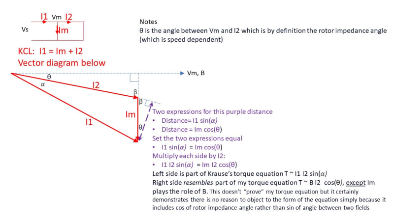
Attached is a vector diagram which proves that I1 I2 sin (alpha) = IM I2 cos (theta)
WHERE
[ul]
[li]alpha is angle between I1 and I2[/li]
[li]theta is angle of the rotor impedance (which is the angle between Vm voltage and I2 current).[/li]
[/ul]
Left side is part of Krause’s torque equation T ~ I1 I2 sin(α)
Right side resembles part of my torque equation T ~ B I2 cos(θ), except Im plays the role of B.
This doesn’t fully “prove” my torque equation is the same as Krause's, but it certainly demonstrates there is no reason to object to the form of my equation simply because it includes cos of rotor impedance angle theta rather than sin of angle between two fields alpha. The fact that B is not present in the result is expected given the circuit used (B is not a vector within this circuit although we know its angle matches Vm). To use the results of the vector diagram to generate full proof that my torque equation represents the same thing as Krause's torque equation would require careful examination of the other constants used in the full equations... I
suspect that can be done but I don't foresee myself spending the time to attempt that. So I will leave it there (*)
I would also note the left side does have an intuitive appeal as alignment of magnets, while the right side
would have intuitive appeal as Lorentz force which acts at radius R to produce torque
if we substitute B for Im.
Going back to my earlier post 21 Mar 23 20:46 using vector cross product I now think it was correct in certain respects and incorrect in certain respects:
[ul]
[li]It was correct to
easily demonstrate I1 I2 sin (α) = Im I2 sin(β) where α is I1 I2 angle and β is Im I2 angle (this is exactly the same as the conclusion of the vector diagram noting that β and θ are complimentary and therefore sinβ =cosθ... but we had reached that conclusion with a few simple cross products rather than all that complicated vector diagram and trig!). That in itself is an interesting transformation and explains some of the variability in which variables appear in textbook torque equations (some have I1 and I2 and some have Im and I2). [/li]
[li]It was not correct to conclude that alpha was related to theta by a pi/2 factor. Theta does carry similar information as alpha in terms of the angle whose sin is needed to compute torque from two current (or field) quantities, but the selection of currents is different and the angles don't have the simple pi/2 relationship that I suggested.[/li]
[/ul]
(*) Why am I leaving it there? I don't believe my torque equation requires proof from the vector equation since my torque equation was already proven by direct comparison to Liwschitz Garik textbook with copy of relevant page attached to my post 21 Mar 23 02:34 (if anyone wants me to walk through an algebraic proof that they're the same, let me know). Also the logic for the equation was clearly shown in an earlier linked paper posted 7 Mar 23 14:21. Being intimately familiar with that paper I firmly believe it's a proof, and it's really simple to understand if you accept the use of Lorentz for this purpose, but you might have to invest some more time to understand why that is an appropriate approach given that the conductors are shielded from airgap flux by the slots, and the force acts primarily on the core.... there are many different proofs of this given in the paper and also excerpts from many texts in the back of the paper which attest that using the force on conductor equation along with Bgap gives the correct result. The paper also includes calculations on an example motor which matched the hp rating pretty closely (based on FLA adjusted for number of parallel circuits, nameplate speed, and the other equation variables B, N, L, R). If anyone has data for a motor they want to try it out on, feel free to post motor details and we can try it out on your motor.