Continue to Site

Eng-Tips is the largest engineering community on the Internet

Intelligent Work Forums for Engineering Professionals

  • Congratulations KootK on being selected by the Eng-Tips community for having the most helpful posts in the forums last week. Way to Go!

Correction factor for cable sizing

Status
Not open for further replies.

farale

Electrical
Apr 7, 2018
36
Dear All,
Power cables installed beside each other, can not tolerate as much current as a single piece of cable.
It is due to thermal effect of each cable on the others.
IEC 60364 and IEC 60502 have specified correction factors for such arrangements.
I am going to put two layers of cables inside underground trench.
Trench will be filled by fine sand. Vertical distance between layers will be 20 cm. Each layer includes 9 cables.
IEC guides me about grouping correction factor for 9 cables in a single layer. But it has nothing about TWO UNDERGROUND LAYERS.
Would you please let me know the correct method? Certainly many people have seen such problem, when sizing their cables.
 
Replies continue below

Recommended for you

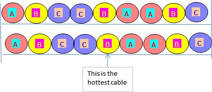
Cables are laid touching each other
 
two_layers_underground_cables_jfbpf0.jpg

If they are single core cables in parallel this order will keep minimum current unbalance. A kind of rack has to be provided in order to keep the distance between layers.
In IEC 60287-2-1 it is a warning about sand filled trough –in my opinion it is good for cable in trench also:
2.2.6.1 Buried troughs filled with sand
Where cables are installed in sand-filled troughs, either completely buried or with the cover flush with the ground surface, there is danger that the sand will dry out and remain dry for long periods. The cable external thermal resistance may then be very high and the cable may reach undesirably high temperatures. It is advisable to calculate the cable rating using a value of 2,5 K.m/W for the thermal resistivity of the sand filling unless a specially selected filling has been used for which the dry resistivity is known.
In order to calculate the minimum permissible current you have to calculate the external thermal resistance T4 of the hottest cable-the lower middle position.
See IEC 60287-2-1 2.2.3.2 Equally loaded identical cables. The distances between conductors are as per Figure 1 – Diagram showing a group of q cables and their reflection in the ground-air surface
 
Calculated for single core 240 mm^2 copper conductor 0.6/1 kV xlpe insulated is 192.8A for 18 cables [ 351 A for one circuit as per IEC 60364-5-52 Table A.52-5].
Calculated for single core 300 mm^2 copper conductor 0.6/1 kV xlpe insulated is 214.6 A for 18 cables [ 394 A for one circuit as per IEC 60364-5-52 Table A.52-5].
So 54% it could be close.
 
Thank you for your reply.
We have 3 core cables both 400V and 6kV. Different voltage levels are laid in separate trenches.
 
For both types of cable the maximum carrying capacity is 34% of rated for one single three-core cable as per IEC 60364-5-52 or IEC60502-2.
 
Thank you for your information.
 
Status
Not open for further replies.

Part and Inventory Search

Sponsor