Continue to Site

Eng-Tips is the largest engineering community on the Internet

Intelligent Work Forums for Engineering Professionals

  • Congratulations GregLocock on being selected by the Eng-Tips community for having the most helpful posts in the forums last week. Way to Go!

Could anyone help me with a material strenght calculation of this operating horn from crashed plane? 10

Status
Not open for further replies.

RedSnake

Electrical
Nov 7, 2020
10,828
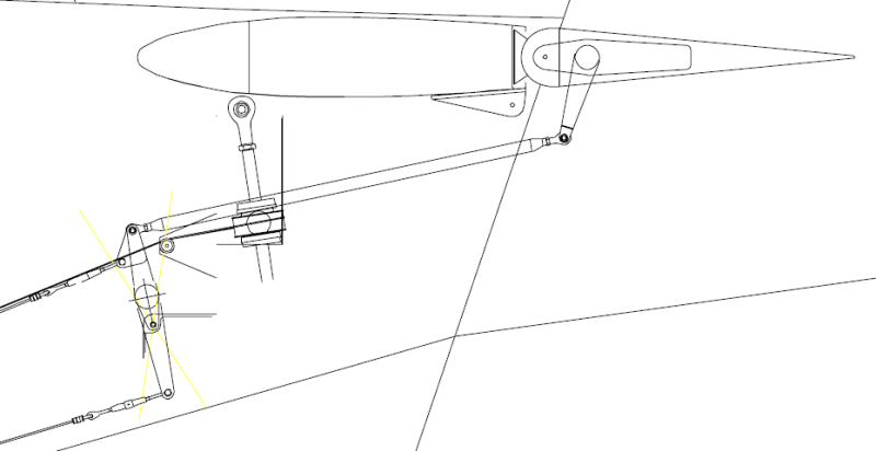
Picture elevator to the left and stabilizer to the right.
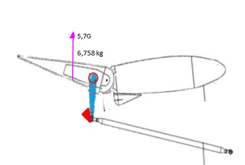
STABH1_pqq4vz.jpg

The red cirkel is a tourque tube on the rudder and have a diameter of 38 mm and the thickness is 1 mm.
The operating horn was a welded box design using steel sheet AISI 4130 in condition N thickness is 1 mm welded against the tourque tube.
On the uperside and sides (3/4 of the circumference) has 30% of the normal materiels strenght(severe lack of fusion).
The last 1/4 can be brittle or have been sheared.
The red triangle is the mechanical stop maximum up.
The relationship between hinge, tourquetube and elevetor edge ca..
0 --------1 --------------------7
Can this construction hold for 5,7 G ???


[img [URL unfurl="true"]https://res.cloudinary.com/engineering-com/image/upload/v1604784211/tips/STABH2_lpxbcz.jpg[/URL]


Properties Metric Imperial
Tensile strength, ultimate 560 MPa 81200 psi
Tensile strength, yield 460 MPa 66700 psi
Modulus of elasticity 190-210 GPa 27557-30458 ksi
Bulk modulus (Typical for steel) 140 GPa 20300 ksi
Shear modulus (Typical for steel) 80 GPa 11600 ksi
Poissons ratio 0.27-0.30 0.27-0.30
 
Replies continue below

Recommended for you

This is from a airplane that crashed :-( so if this is the wrong forum where should I ask??
Just trying to figur out if the strength between the horn and tourgue tube on the elevator is okay for that construction.
The right part is the stabilizer.

Best regards A
 
Are you sure your on about the right bits?

rudder is usually connected to the fin and elevator connected to the stabiliser.

Rudder does yaw forces and elevator does pitch.

You have to also see what the certification class is of the aircraft. At 5.7g your into unlimited aerobatic aircraft or military.

Utility certified aircraft will be 2.5G max clean and 2G with flaps down.

I am pretty sure it won't be strong enough to handle 5.7 G there are very few civilian types that are capable of taking those sorts of G. So I am not really surprised it crashed. I say this as a pilot and my condolences if it was someone close to you that was in it.

 
Sorry my mistake.. in this picture stabilizer to the left and elevator to the right.

elevator_1_nynqmt.png


The aircraft is certified in accordance with CS-23, which i.a. means that the permissible load factors are +3.8 g and -1.5 g. A safety factor of 1.5 must be used, which means that the ultimate load to hold is at least +5.7 g and -2.25 g, respectively.

The flapps where in at the time.

Best regards A4


Yes, someone I have known for 37 years and worked with for 30 and had a relationship with for the last 15 years.
I miss him so much.
 
Ok your on about ultimate load which is also limited by Vma and also rough airspeed.

CS 23 has several sub classifications not all types under it will have the same load certification limit. And to make matters worse older types will have been grandfathered into it with dispensations over certain things. The only way you will find them out is from the type approval paper work.

If the aircraft is above Vma then all bets are off. Usually when these things fail its due to a very aggressive pull up from a loss of control and the aircraft speed is way over Vmo over mind Vma.

What speed was it doing? And what were the limiting speeds?

What model of aircraft we on about?
 
No, what I want to know is, how to calculate the strength between the lever and the tourqe tube and what force it is exposed to if the elevetor is against the mechanical max stop upwards and the force on the elevator 5.7 g.

To see if the strength reaches the expected value.

Or how much force on the elevator that is required to tear off the lever in the attachment to the tourque tube?


I do not know much about flying and airplanes and I have no exact information about the speeds etc.

Best regards A
 
You need a lot more detail on the precise connection detail between the arm and the tube.

Also how the individual bits were actually attached (welding etc)

Then you're going to need either a set of test to destruction or a range of loads or a very detailed FEA analysis.

From what I can figure out this looks like a very odd / delicate piece of jointing and design for such a crucial part of an airplane.

Remember - More details = better answers
Also: If you get a response it's polite to respond to it.
 
I know it's complicated. But unfortunately I have no alternative but to make a simpler calculation and start from what I have. If it then turns out that there is a risk that this does not measure up. Can one perhaps demand that a better calculation with correct values ​​will be made.

The red areas is the weld.

horn_2_hko1d5.jpg


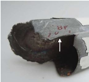
Picture of the brake.
The weld between the red marks has fusion of 10-50% and the cirkular weld on top is as bad.
STABH3_aadysf.jpg

horn_1_met2sr.jpg


Best regards A
 
No idea I'm afraid. This looks too complex a joint to do any hand calculations that are going to be accurate.

The fact that the part appears now to be badly made and a lack of weld QA/QC complicates things beyond belief.

It does look very thin and I'm not sure what I'm looking at in that photo.


Remember - More details = better answers
Also: If you get a response it's polite to respond to it.
 
the problem is that the elevator moves and the force moment creating the torque is L=1/2rhoV2Cl Just giving a g force of 5.7g doesn't give enough info to get the torque.

Which is why there is Maximum manoeuvring speed limitation given above that speed if you use full deflection of the controls things will start plastically bend and fail ultimately fail.

These failure usually occur when the aircraft has entered a spin or a spiral dive and during the recovery the aircraft has a very nose down attitude and accelerates extremely quickly with a windscreen full of ground. The pilot then hauls back on the stick as hard as they can at over the maximum manoeuvring speed. Then the tail comes off or elevators control rods detach. Which you can still save yourself by using the trim tabs but the pilots that are switched on enough to do that won't be the ones to get into the situation in the first place.

And to be honest the lift from the elevator in your diagram will be going the opposite direction to the G force. The diagram shows a pitch down control input which your limits are -2.25g for.
 
And without knowing the aircraft type we can't actually find out what the original certification standard was for. I would be extremely surprised if it is those limits you have given which only apply for newly certified CS-23 aircraft. Which I might add the DC3 comes under that heading as does the Cessna 150 and my old aircraft Jetstream 31/32. Out of the 3 mentioned only the Jetstream could do over 2.5g clean.
 
It is The Accident Investigation Board that claims it is certified CS-23.
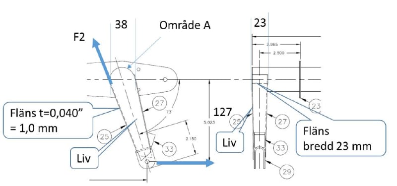
The only calculation I have seen is
STABH4_duenim.jpg


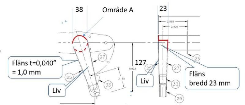
The lever can be seen as a box beam with flanges and life. As the flanges converge towards the point of attack of the force, the transverse forces become largely non-existent. Which means that the function of life is mainly to prevent cracking of the printed flange. There were no traces of buckling on the lever, so the welding error that was located in the connection between flange and life becomes insignificant.

Flange cross section = 23x 1 = 23 mm2
Yield strength 4130 = 50 daN / mm2
Flange breaking load (F2) = 23x50 = 1 150daN
Moment = 1150x38 = 43 700 daNmm
F1 = 43 700/127 = 344daN
Gear ratio for the steering wheel approximately 5: 1
Steering wheel power = 344/5 = 68.8 daN for breakage
(Assuming that the entire steering wheel power goes only to the right elevetor.
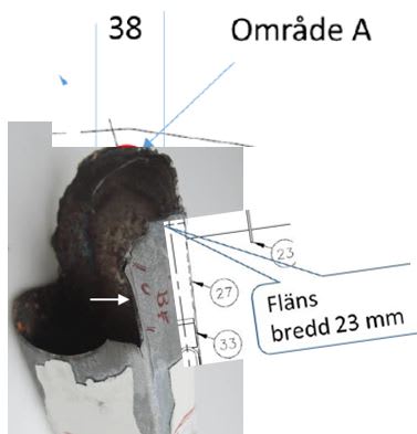
In addition, material is added in area A
The lever has thus had good strength despite the welding error.


So if you push the steering wheel forward pitch down by 60 kg you would break the lever.!?!

I might add that I do not understand why he put F2 vertically upwards. According to those who did the material investigation, the crack began at a 90-degree angle from the drawn F2 (the wite arrow in picture abow), the area he thinks is uninteresting.

Maybe I asked the question the wrong way.
I would like to simplify it.
If the plane is locked on the ground and you press with a load on the underside of the elevator and the lever rest against the maximum stop or from the top and it rests against the minimum stop.
How much force do I then have to apply to break the lever from the tourque tube?
No speed involved.
Is there any other way to calculate breaking load ?

MVH A
 
Redsnake,
You might want to re post this in the Aircraft engineering forum, forum 2, and red flag this post I think you will get better answers there.
B.E.

You are judged not by what you know, but by what you can do.
 
Redsnake,

Why are you doing this? To check the accident board’s calcs/conclusion?
It appears you are not an experienced aircraft stress analyst. No one on this web site is going to do a detailed analysis of this for you (nor should they). Way too much detailed info is required. Suggest you hire an experienced analyst.
 
Your text also appears to be suffering from an non engineering translation which means it doesn't make sense.

If failure of this part led to a fatal crash then it will be investigated by the relevant authorities. If you tell us more we can provide some better insights but at the moment it's all a big muddle.

It doesn't look like a well engineered part to me and I'm surprises to see something like that on an aircraft.

Remember - More details = better answers
Also: If you get a response it's polite to respond to it.
 
To SWComposites.
I have never asked for an detailed analysis, just a simpel strength calculation.
It may seem so, but I have only answered the questions I received from you, It is you who want to make it advanced.

If the Accident Investigation Board can make one so simplified calculation as shown above.
Mine need not be more advanced.
I had expected that they would have made a real calculation with the manufacturer's CAD drawings as a basis, but that is not done.

I have enough technical knowledge of welding and metal strength after working in a press workshop for 33 years, even if it is not my specialty, to feel that this has not been properly investigated.

I do not check the Accident Investigation Board's calculation, because the calculation I am asking for has not been made by them, as far as I know.

The calculation I showed here I do not question, I just do not understand it.
I thought these types of sites were for help and understanding, but maybe I was wrong?

Best regards A
 

If you mean the bold text, I can not clarify it. I did´not write it myself.
It comes from the Accident Investigation Board.
But the word life might meen something that is stiffening !?!

Model
GA8-TC 320
Year of manufacture
2012

Best regard A

 
This one?


Sounds like it stalled as the jumpers started to get ready and moved to the back of the plane.

Jump pilots are a bit of a special breed.


Remember - More details = better answers
Also: If you get a response it's polite to respond to it.
 
Status
Not open for further replies.

Part and Inventory Search

Sponsor