Continue to Site

Eng-Tips is the largest engineering community on the Internet

Intelligent Work Forums for Engineering Professionals

  • Congratulations cowski on being selected by the Eng-Tips community for having the most helpful posts in the forums last week. Way to Go!

Could you get this to work?

Status
Not open for further replies.

Prestressed Guy

Structural
May 11, 2007
390
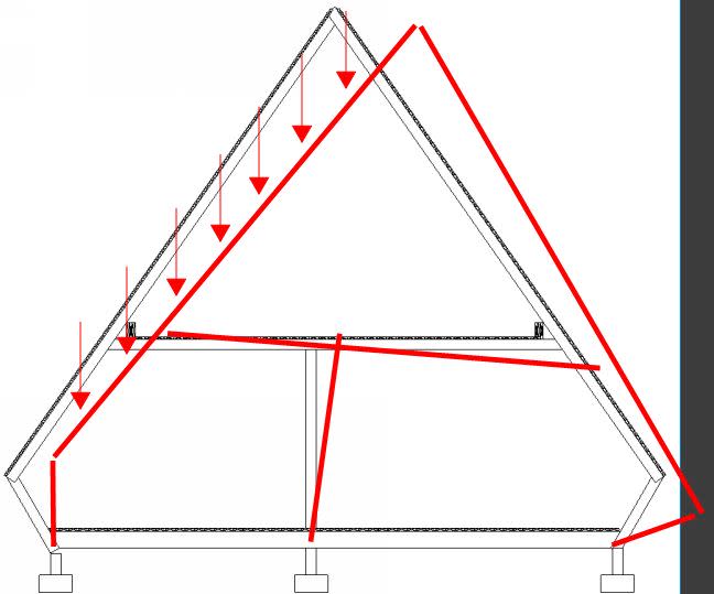
This is an interesting one. Yesterday I was asked to look at a house built in the 1970's and have attached the basic frame section. The frames are constructed of 4x6 lumber @ 42" oc and 2x6 T&G decking for floors and roof. The loft floor stops about 10' from the front wall of the structure and there are interior walls in the plane of the frame at 10'-12' spacing. The longitudinal beams shown at the edge of the loft are (3) ply 2x10's with offset butt joints. I could not find any locations with 2 plies butted at the same location so I assume they are 16' long with 5'-4" offset.
 
 http://files.engineering.com/getfile.aspx?folder=bfe192c9-b847-4afd-b0e1-abcb10dd5821&file=basic_frame.png
Replies continue below

Recommended for you

It looks laterally unstable. Maybe the interior walls in the plane of the frame are acting as shear walls to provide the lateral support.
 
Looks like it shouldn't work... do you have any moment transfer at the haunch?

Dik
 
When I walked in my first thought was "What have I gotten myself into?" and 2nd "Maybe I should just leave". ;>)
Cal91. Yes, the interior walls are providing lateral support.
dik. I agree, it looks like it should not work but it has been there for 50 years. It was a windy day and I did not perceive any wind induced motion while upstairs. I also did some rhythmic bouncing and the loft was stiffer than the main level (and stiffer then most floors in my own house for that matter.
To answer your second question the connection at the loft/rafter does not have any moment capacity. in fact, I would say that it has limited gravity capacity. See attached photo.
 
 http://files.engineering.com/getfile.aspx?folder=5db7e557-619c-4a1e-aceb-c3cfbd67293d&file=20171017_174934_resized.jpg
Performance is an excellent indicator of success
 
ash060. It is pretty hard to tell someone that their home too unstable to stand when it has been continually lived in for nearly 50 years. Anyone care to comment on load path and joint free-body diagrams? I have my ideas but would like to hear what others come up with.
Assume that it is stable (given 50 year history).
 
Seems like you can't get around there being some moment fixity at the joints, particularly at the exterior foundation/exterior wall joint for this to be stable.
 
I disagree. I think the frame provides vertical stability without any moment connections. The frame is stabilized laterally by the roof diaphragm / interior shear walls.

It's analogous to a simple supported beam on two pinned columns is vertically stable, and laterally stabilized by diaphragm / lateral force resisting system.
 
Haydenwse

I agree that the structure works, that was the intent of the comment. If the structure functions as intended, the design is acceptable. It is like it had a fifty year load test, even though the load path is not apparent it has one.
 
Look at the photo. I would not give that connection any moment capacity. The joints are all pin connected. Assume that the frame cannot deflect laterally due to interior partition walls that are attached to the roof and floor decking which prevents lateral movement of the upper floor relative to the lower floor.
 
I think so, but I would have to add another beam/joist system over the top of all three footings, and below the existing floor joists so that the end diagonal members could have a fixed base - well, somewhat fixed anyway.

Mike McCann, PE, SE (WA)


The crawl space has girders under the floor joists. The floor / joists are 4x8 @ 42" oc. In alignment with the wall/roof frames The sketch is just to show the basic geometry but there are no provisions in the connections that could be interpreted to have moment capacity in wood construction.
 
In my opinion it is simply an A-frame, supported on the little struts, and stabilized by the walls/floor

The main rafters are bending at the loft connection, which ties each side together. (the photo you attached)

 
No. As currently drawn, the structure is unstable laterally.

Mike McCann, PE, SE (WA)


It's stable when the diaphragm and interior walls are accounted for.
 
Still bother me as these structures typically have large window walls at one end with little to no shear capacity.

And, the only stabilizing triangles I see are above the loft... nothing below that.

I still do not like it.

Mike McCann, PE, SE (WA)


It seems everyone is overthinking it. The basic frame with the rafters and bottom chord is obviously stable. The odd little splayed studs can't go left or right or both without bending the lower floor joists and bending the tails of the rafters. Provided that the bending resistance is there in the joists and in the rafter tails, pin joints everywhere in this arrangement are eminently stable, as has been demonstrated for 50 years. If you don't believe it, get out your popsicle sticks & try it.
 
I vote unstable save for the effect of interior and exterior shear walls. And I wouldn't be too thrilled about having my E&O insurance tethered to the thing unless I'd identified and evaluated those shear walls with some care. What's the issue that got you looking at this thing in the first place? Owner fishing for an open floor plan?

I suspect that the frame derives much of its gravity load "stability" from the fact that the gravity loads appear to be distributed pretty symmetrically.

My spidey senses lead me to speculate that something is missing from this picture though. If stability is really as fragile as it appears, I would have thought this thing pretty tough build in the first place without resorting to shoring etc.

I want a picture from the outside. Is it red like Papa Smurf's hat?

I like to debate structural engineering theory -- a lot. If I challenge you on something, know that I'm doing so because I respect your opinion enough to either change it or adopt it.
 
Gravity stability - bending rafter tails

Lateral stability - floor and cross walls.


A trussed roof spanning between two side walls isn’t stable either without crosswalls. Are we going to fail that scenario too?
 
In the absence of moment connections, I disagree with the notion that the rafter tails in bending address gravity stability. Below, I've drawn a racking mechanism that involves no flexural deformation and no axial deformation (almost, more on that later). In my opinion, this serves as proof that the thing is unstable in the absence of shear walls etc as described above. And this is considering the rafter tails to be rigid. As anyone who's designed tail bearing trusses can attest to, the rafter tails are anything but rigid and often insufficiently strong. They're sketchy at the best of times.

There is a small flaw in my argument here. The mechanism below would require the middle post to shorten. I've shown that below, greatly exaggerated. So the frame would be stable mathematically if the collar ties were sufficient rigid flexurally. But, then, I can't fathom a structural engineer worthy of the title putting any serious stock in that.

I also contend that the situation is quite different from that of a common house truss on plumb walls. With plumb walls, unbalanced gravity load does not produce a significant tendency towards lateral movement (racking). That's a pretty fundamental difference. Just ask the steel erectors that work on the Frank Gehry stuff.

C01_elkher.jpg


1200px-The_Dancing_House_in_Prague_acbaed.jpg


I like to debate structural engineering theory -- a lot. If I challenge you on something, know that I'm doing so because I respect your opinion enough to either change it or adopt it.
 
Status
Not open for further replies.

Part and Inventory Search

Sponsor