Eng-Tips is the largest engineering community on the Internet

Intelligent Work Forums for Engineering Professionals

  • Congratulations waross on being selected by the Tek-Tips community for having the most helpful posts in the forums last week. Way to Go!

Cross Hole Single Datum Axis tolerance zone

Status
Not open for further replies.

sendithard

Industrial
Aug 26, 2021
166
0
0
US
I don't understand a positional callout when a part still has rotation freedom.

For example, 7.10.3 in 2018 std states a primary cylindrical datum is always associated with two theoretical right angled planes.

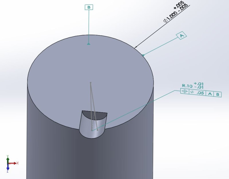
My question is when a hole(diam tol zone) or a slot(planer tol zone) has a position of A|B and rotation is still on the table how do you define the plane or axis to use as the center of the tolerance zone....see below pics...For the model below, you can see a poorly drilled hole, one could assume the tolerance zone axis goes thru the bottom of the hole or the top of the hole, I guess you could even fit one thru the mid-point of the hole axis. Another method would be to set it up as a best fit to minimize the deviation as kindoff seen in the last picture.

Thanks for any help.

model_pb0fab.jpg
single_datum_axis_ukynga.jpg
center_plane_slot_xphwe2.jpg
 
Replies continue below

Recommended for you

When there is no rotation constraint about a primary datum axis, there are still two mutually perpendicular planes of the datum reference frame intersecting at that datum axis. The datum reference frame is three orthogonal planes and the third one is datum B. The true position axis and the position tol. zone which is centered to it are fixed relative to the DRF according to the basic dimensions - the basic distance and the implied 90°. In this case it doesn't really matter at what angle the tolerance zone is relative to the two planes intersecting at the axis as long as it is at a right angle to the axis and parallel to datum plane B. Since there is an available rotational degree of freedom you can rotate the part around the datum axis and essentially by doing so, around this entire DRF + tol. zone structure, until the actual axis of the hole fits the cylindrical tol. zone and the measured position value is minimized. So yes - you were right that there is a certain best-fit aspect to it.
 
Bur,

Thanks for the reply, interesting it came from you bc this will be a part of my next video as it may require a best fit I think for GOM. I'm working on a program that doesn't require the part to be run on both the CT and CMM.

GOM will not create these right angles planes unless you complete the A|B structure and give it that final A|B|C relationship. It doesn't simply best fit/minimize the callout for you, it actually won't even let you measure the above callout. You need to fully define this by using the CAD cross hole cylinder as datum C for rotation or you have to manually create a line that intersects with the midpoint of the real feature, which bc you depart from the CAD feature it isn't parametric/repeatable.

I have more to investigate, thanks for the input, very helpful.
 
sendithard,
Does Gom have this problem only when a last rotational DOF is unconstrained?
How about a datum reference frame in which 5 degrees of freedom are constrained and only one translation remains free?
Such datum referencing scheme could be used for a location refinement of surface profile in a specific direction, in a callout used as a second segment in a two single segment profile tolerance.
 
sendithard,
In the context of the points you brought up here on 2 Aug 22 21:52,
Have you tried seeing how Gom performs at inspecting a simultaneous requirement according to the ASME Y14.5 standard? I am thinking specifically about cases where a rotational degree of freedom remains unconstrained for two requirements that reference the same datums in the same order, but the simultaneous requirement rule has the features aligned anyway, by fixing their tolerance zones or boundaries relative to each other in rotation. See the below figures from the 2009 version. Consider fig. 4-40 (upper case) where the rule applies. Suppose that both keyways were accurately centered to the datum, but much less accurately aligned to each other.
In this case both measured position values could be about zero if evaluated separately (as in the SEP REQT case from 4-41), but they should utilize some more tolerance when mutual alignment is considered.
Ideally, the software would make some rotational "best fit" to find an orientation of the part about datum axis A and both of the aligned tolerance zones/boundaries at which both measured position variations would be minimized. But does it work this way?

Screenshot_20220812-204504_Drive_iyp1rg.jpg
 
Status
Not open for further replies.
Back
Top