Eng-Tips is the largest engineering community on the Internet

Intelligent Work Forums for Engineering Professionals

Datum as plane tangent to two cylindrical surfaces 2

Status
Not open for further replies.

tw_0407

Mechanical
Mar 19, 2023
4
0
0
US
I have a part with two partial cylindrical surfaces and I want to make a datum that is the plane tangent to the two surfaces, as the mating part has a flat surface that is seated up against them.

Part is similar to this example I mocked up:
datum1_ojheja.png


And I want the datum to be tangent to both surfaces, like so:
datum2_lendmk.png


Can I just sketch a line between them on a top-down view like in the above picture, and attach a datum to that?
 
Replies continue below

Recommended for you

"The regurgitation of the standard isn't explaining..."

I could explain more, but I charge triple if I have to train a "D&T Consultant" with such rooted misconceptions as you just demonstrated.

Better go straight to the source and read all about it in Y14.5.
I'll only give you this tip - start by looking up what two symbols are used to identify a datum feature and when each of them is appropriate. Then ask yourself how do you know that one is more appropriate than the other for any particular case. That should lead you in the right direction.
 
Explain why your stating that using a datum simulator to locate the tangencies so the tangencies can be used as simulators for datum target lines and those datum target lines used to locate the part on the datum simulator to establish a datum (theoretical) makes sense.

Not just for me, but for the OP you have ignored for another attack on my character.
 
3D,
Your description of what you claim to be my statement adds complexity by making up a loop that isn't actually there.
The standardized method should have already been clear from what I did say, but here is your spoon feeding:

The datum feature simulator - an inspection fixture component or a virtual equivalent, simulates the datum - in OP's case, a plane, and contacts the datum feature - a designated feature on the part.

Generally, the datum feature is identified on the drawing by either a datum feature symbol or datum target symbols.
The drawing maker chooses between those two symbols according to the type of interface intended between the datum feature and the datum feature simulator as explained below.

- If it is required that the entire* datum feature surface can potentially mate with the datum feature simulator, only a datum feature symbol is used (*- another proper use of the symbol is with a limited area or length indication to identify a relatively large portion of the surface). That results in a particular alignment of the part to the datum as the measurement origin. This is not the OP's case.

- If it is intended to mate the simulator and the datum feature by partial contact at some elements (i.e. points/lines/relatively small areas) of the datum feature surface with some kind of distinction of those elements from the rest of the feature's surface, datum target symbols are used with an appropriate dimensional definition for these targets. This results in a different type of alignment of the part to the datum as the measurement origin. This application suits OP's case.

In OP's case, the distinction of the two contact lines from the rest of the feature is by them needing to lie nominally parallel to each other on a single plane that is tangent to both curved portions. This would be communicated by a phantom line representing the tangent plane on the drawing. Essentially this means implied basic 0° dimensions for the two parallel (non-skewed and non-intersecting) datum target lines. Since no basic spacing dimension would be given, the actual contact lines (realised as some quantity of contact points lying approximately along the parallel lines, due to actual part imperfections) would be understood to depend on the actual surface peaks.

You are welcome (for the free training).
 
If it is intended to mate the simulator and the datum feature by partial contact at some elements
That is the part you made up. It is not part of the standard.

This would be communicated by a phantom line representing the tangent plane on the drawing. Essentially this means implied basic 0° dimensions for the two parallel (non-skewed and non-intersecting) datum target lines. Since no basic spacing dimension would be given, the actual contact lines (realised as some quantity of contact points lying approximately along the parallel lines, due to actual part imperfections) would be understood to depend on the actual surface peaks.

This is another part you made up. It is not part of the standard.

Making up your own version of the standard when there is a method already present is not educational. It is to save face over misconstruing what the standard clearly states.

As soon as a phantom line is to represent a plane that makes contact it has defined a plane and there is no need for it to be phantom or to derive any further features from it. That is why it wasn't required to say that there are two target areas on the flat areas in Figure 7-52.

I describe what is shown in Figure 7-42 Possible Datum Feature and True Geometric Counterparts From Three Pins Used as an Irregular Feature of Size, the standard method.
 
Speaking of the usage of a standard method, isn't the OP's case similar, in principle, to what is shown in fig. 7-58 in 2018?

This means that the top view should show a phantom line labeled as datum target A1 and no depiction of that datum target should be given in other view to make it clear that the datum target is a plane and not a line. Also, no two datum target lines should be shown at the surface peaks.

 
It's not a target. It's not required for the same reason targets aren't required for any of the examples in Figure 7-42 or Figure 7-52.

I note that Figure 7-52 has a count called out but Figure 7-42 doesn't.

Conshisltency ithn't thair shtrong shoot. (in the voice of Mel Blank performing Daffy Duck.)
 
It is not a target by the datum target definition (which I agree shouldn't be the case), but it is in line with the approach used in the existing figure and the text associated with it.
 
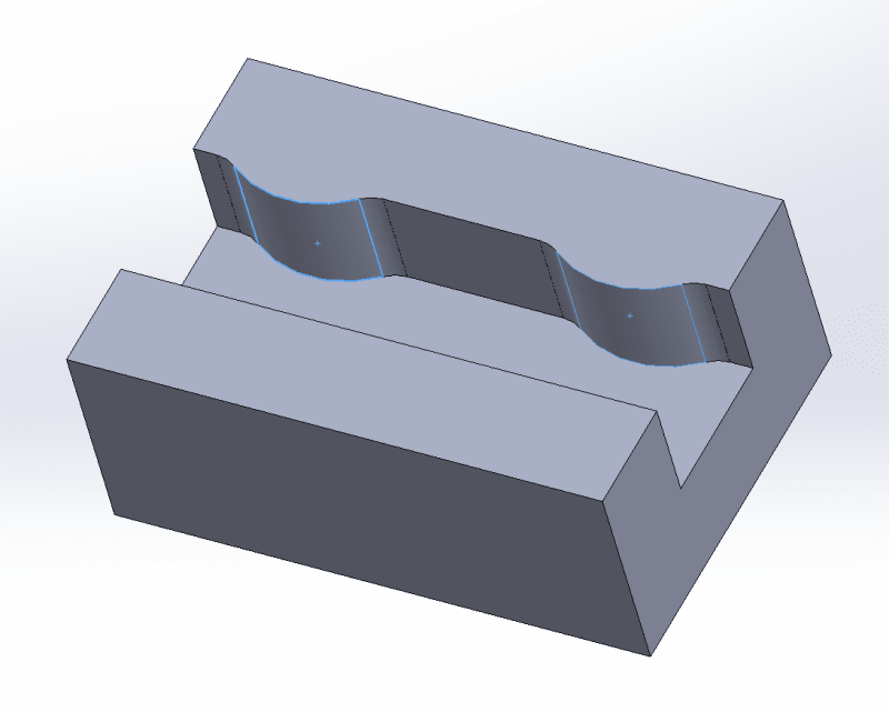
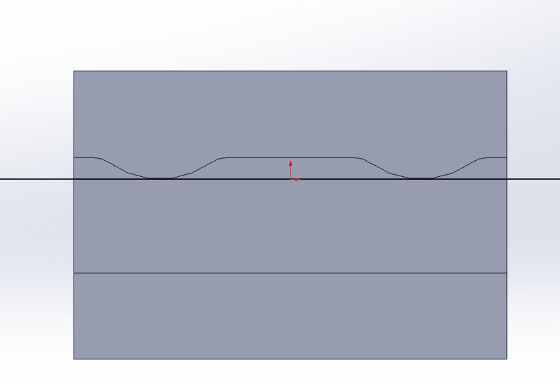
It contacts two places, so is it B1-B2? It's not necessary as other examples in the standard show.

Who was it who added the "datum target plane" verbiage to the 2018 standard?

Same person who failed to add it to Section 3, DEFINITIONS and also failed to add it to the NONMANDATORY APPENDIX A PRINCIPAL CHANGES AND IMPROVEMENTS?
A-5.1 Edited Definitions
The following definitions were edited for added clarity and without intent of change to the meaning: angularity; boundary, least material (LMB); datum target; feature; free state; irregular feature of size; and runout.

A-5.2 Added Definitions
The following definitions were added: continuous feature, continuous feature of size, interruption, represented line element, restrained, and true geometric counterpart.


A-9.12 Datum Target Requirements and CAD
Application of datum target dimensional requirements and accommodation of CAD capabilities have been added in para. 7.24.3.

Here's the edited definition:
3.21 DATUM TARGET
datum target: the designated points, lines, or areas that are used in establishing a datum.

See what is clearly missing?

No figure for Datum Target Plane:
6-8 Datum Target Point
6-9 Datum Target Line
6-10 Datum Target Area

Further, everwhere else in the standard reflects this: 7.24.4 Datum Planes Established by Datum Targets, not "datum target planes are established."

No wonder Burunduk is so hot and bothered. Probably wants to show off a new toy from his hundreds of hours of pouring over the standard going line by line and word by word. However, he wants to establish the mutually tangent plane to create datum target lines to create a datum plane that is a mutually tangent plane.

However, it is not required and doesn't match the OP case.

Since it is missing from all other places in the standard I take it as nothing more than a typographical error or an unauthorized change made without committee review.

Once again:

Conshisltency ithn't thair shtrong shoot. (in the voice of Mel Blank performing Daffy Duck.)


The standard is indeed inconsistent, I am not saying otherwise. It defines 3 types of datum targets (points, lines, areas), however it directly uses the datum target term for at least one more type of object - plane. See para. 7.24.1.

Even the title of that paragraph, "Establishing a Center Plane From Datum Targets", seems to conflict with the current definition of datum target, if planes are going to be used to as V-shape true geometric counterpart.
 
That's the paragraph I was referring to. Now you've spoiled the surprise for Burunduk if he had not previously noticed it. He could have had hours of looking to find it.

The term appears in exactly one place, not defined, no matching figure, and no mention of it being added and I would say it's not simply inconsistent, it exposed unnecessary carelessness in creating this version. Who was responsible for that edit? Why didn't they tell anyone else they had done it? If they did tell anyone, why didn't any other sub-committee bother to deal with it?

One can establish datum planes from datum targets, that is the entire function of datum targets, to establish datums; this is not the same as creating a separate datum feature from datum targets.
 
3D,
There are already 3 people (Garland, pmarc, and myself) suggesting the use of datum targets here, because datum targets are the standard method to relate a part to a measurement reference (datum) by using local elements such as points, lines or areas on the datum feature. If you think I made that up and it's not part of the standard, you haven't really used the standard.

As for the other part you claim I maid up; datum target lines represent lines of contact between the datum feature and the datum simulator, so in the OP's case a graphical clarification that the targets on the peaks are defined by contact with a single planar simulator would do. What part of it is made up?

pmarc,
I see no application of a "datum target plane" in fig. 7-58. It's all about datum target points and lines.

Screenshot_20240822_095625_Drive_wv1d8f.jpg


The idea of a "datum target plane" does appear in Y14.41 in the figure you posted on another thread, to which I referred in my initial reply to the OP above.
 
Burunduk,
I did not say fig. 7-58 shows datum target plane application. I said this term is used in para. 7.24.1, where it is explained how the figure needs to be modified to define datum target planes instead of datum target lines. But how can one define datum target planes if planes, per the definition, are not possible choice for datum targets?

I hope this clarifies what I meant.
 
That example is intended to establish a datum plane that is not coincident with either of the defining planes.

You want to use a plane that is coincident with the datum plane to define the datum plane. As all the other examples I have given show, this is neither required nor supported.

That is a problem with ad hoc proposals that don't go through the entire committee review process.

 
pmarc said:
I did not say fig. 7-58 shows datum target plane application. I said this term is used in para. 7.24.1, where it is explained how the figure needs to be modified to define datum target planes instead of datum target lines. But how can one define datum target planes if planes, per the definition, are not possible choice for datum targets?
I hope this clarifies what I meant.

pmarc and all,

I think you went a little too deep and too fast for my current level of understanding, but anyway, my follow up question is: if we remove the word "target" from the 7.24.1 would you say now that the paragraph is a little more consistent with the rest of the document (without missing datum target plane definition (because you don't really need such a term)?

or we can use the datum CENTER plane term?

7.24.1
If a datum target plane V-shaped true geometric counterpart is required, B1 and B2 would only be shown in the top view. On the model, the V-shaped simulator is represented by supplemental geometry tangent to the cylindrical feature, and the datum target is attached by a leader.

 
Looking at ASME Y14.5-2018, Figure 7-13 Inclined Datum Feature, one sees that the intersection of two planes that are not mutually perpendicular creates the same control as is being discussed. Since the two contacts in 7-13 are on surfaces of different extents they are given a priority in the datum reference section of the feature control frame.

If, as in the datum target line example, it was a round feature then the appropriate callout using datum planes would be to have both, separated by a hyphen.

The business going on in 7.24.1 is simply to save using a hyphen and an extra character in the feature control frame. Same amount of drawing of datum indicators, more complicated symbols; probably someone in the Y14.41 committee is on the section 7 committee and just added it.

"datum center plane" applies to the center of widths.
 
pmarc said:
I said this term is used in para. 7.24.1, where it is explained how the figure needs to be modified to define datum target planes instead of datum target lines.

Ok, I see it now.

pmarc said:
But how can one define datum target planes if planes, per the definition, are not possible choice for datum targets?

Maybe the person responsible for adding that text thought it was a good idea to make another extension of a principle, after there is already a type of datum target that is not a point, line, or area (and not a plane either) exemplified elswhere in Y14.5. You probably know which example and additional datum target type I'm talking about.

I don't find those extensions of a principle useful. To be consistent, the standard(s) should have stuck to datum targets as representations of the form of the contact between the simulator and the datum feature. For example, if I want to communicate that there needs to be contact between a planar datum feature and datum-simulating pins along lines, as in Figure 7-60 (targets B1&B2), I use datum target lines, not datum target cylinders to represent the form of the simulators. Similarily a datum target plane is not required to define line-contact with a curved feature.

...

3D said:
You want to use a plane that is coincident with the datum plane to define the datum plane.

No, I want a planar simulator to simulate a datum plane and contact the double-curve datum feature along 2 lines.
 
"planar simulator to simulate a datum plane"

See. That's all that is required. Already demonstrated in the sections on irregular features of size as datum features. Those contacts are also lines, but those lines aren't taken as individual datum targets.

A plane is required to be find the shared tangent to two cylindrical features or an oriented plane to find the exact tangent to an individual curved surface.

Individual lines that have no control of that shared tangent do not fit that requirement. Moreover, there is no need for a cylindrical simulator to find a mutual tangency to a cylindrical surface and clearly all examples of datum target lines have cylindrical inspection equipment.

I am sure the OP and greenimi don't know which example, so I'll let you tell them what acorn you have found.
 
If the idea that the datum target form should match the contact, then the lines shown for B1 and B2 in Figure 7-58 of ASME Y14.5-2018 are incorrect. That tangential contact between a line and a cylinder is a point and, by the flawed reasoning, should not be lines at all and should be datum target points - the only contact possible for that arrangement.

But that is a logical contradiction, showing the reasoning for the other argument is also flawed and should be rejected.
 
If you want to do it the easy way, just use the first ISO view you show and place a Datum A marker on one of the curved surfaces and a Datum B marker on the other, then you'd call out A-B as primary, C as secondary, and D.
 
Status
Not open for further replies.
Back
Top