Eng-Tips is the largest engineering community on the Internet

Intelligent Work Forums for Engineering Professionals

Datum as plane tangent to two cylindrical surfaces 2

Status
Not open for further replies.

tw_0407

Mechanical
Mar 19, 2023
4
0
0
US
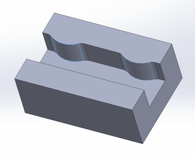
I have a part with two partial cylindrical surfaces and I want to make a datum that is the plane tangent to the two surfaces, as the mating part has a flat surface that is seated up against them.

Part is similar to this example I mocked up:
datum1_ojheja.png


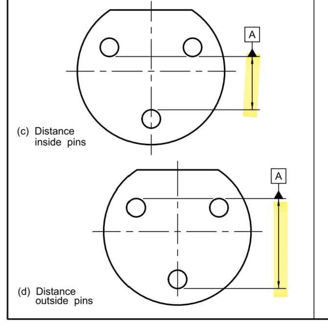
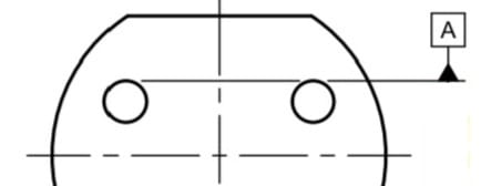
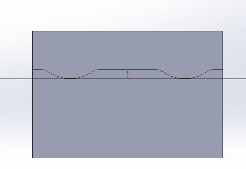
And I want the datum to be tangent to both surfaces, like so:
datum2_lendmk.png


Can I just sketch a line between them on a top-down view like in the above picture, and attach a datum to that?
 
Replies continue below

Recommended for you

3D said:
Already demonstrated in the sections on irregular features of size as datum features.

As I already explained, those irregular datum feature of size examples show a datum feature symbol associated with a dimension line, which is a legitimate use for that symbol. Placing the datum feature symbol on a representation of a theoretical plane is not.

Different datum target lines associated with the same datum reference or different datum references that appear in the same feature control frame are never "individual" as you say. They are related to each other by basic dimensions.

A representation of a common plane in the OP's case could invoke the implied basic dimensions that are required.

A basic angle between auxiliary drawn lines passing through datum targets could define a v-shaped simulator a la 7-58.

There could also be an inverse case in which an auxiliary drawn circle with a basic diameter would contact a v-shaped datum feature on two datum targets at the tangencies, obviating the need to attach the datum feature symbol to a representation of a non-integral cylinder or invent another type of a datum target (cylinder).

3D said:
If the idea that the datum target form should match the contact, then the lines shown for B1 and B2 in Figure 7-58 of ASME Y14.5-2018 are incorrect. That tangential contact between a line and a cylinder is a point and, by the flawed reasoning, should not be lines at all and should be datum target points - the only contact possible for that arrangement.

But that is a logical contradiction, showing the reasoning for the other argument is also flawed and should be rejected.

That's why I said "to be consistent...", but is it? In so many occasions you said that Y14.5 isn't consistent, and now you base an argument on the assumption that it is? That's not very... consistent. Of you.
 
greenimi said:
my follow up question is: if we remove the word "target" from the 7.24.1 would you say now that the paragraph is a little more consistent with the rest of the document (without missing datum target plane definition (because you don't really need such a term)?

The term "plane" in that context is intended to say that someone may want two planes as datum targets like here , instead of the two lines B1 and B2 in figure 7-58. Either way they still relate the part to a plane datum (coincident with the ZX plane of the coordinate system shown in both cases).
 
"As I already explained, those irregular datum feature of size examples show a datum feature symbol associated with a dimension line, which is a legitimate use for that symbol."

That is false. ASME Y14.5-2018 Figure 7-42 c and d are not associated with any dimension.

You argue for two different interpretations at the same time. That isn't inconsistent, that is contradictory.
 
From 6.3.2 Datum Feature Symbol:
"The triangle of the datum feature symbol may be applied to the feature surface, surface outline, extension line, dimension line, or feature control frame as described in paras. 6.3.2.1 and 6.3.2.2. The datum feature symbol shall not be applied to center lines, center planes, or axes."

There is no indication that attachment of the symbol to a representation of a theoretical plane or any non-integral element is a valid application. There is indication to the contrary.

Further, in 6.3.2.1 Datum Feature Symbol Application in Orthographic Views:
"(d) placed on the dimension line or an extension of the dimension line of a feature of size when the datum is an
axis or center plane. If there is insufficient space for the two arrows, one arrow may be replaced by the datum
feature triangle. See Figure 6-4, illustrations (a) through (c), (f), and (h); Figure 7-40; and Figure 7-42, illustrations (c) and (d)."


Judging by the above texts, clearly those are considered dimension lines:

Screenshot_20240823_175238_Drive_yr4mmu.jpg


3D said:
That is false. ASME Y14.5-2018 Figure 7-42 c and d are not associated with any dimension.

The false statement is yours.
 
Those are dimension lines nevertheless.
Those are cases of irregular features of size used as datum features, having very little to do with OP's problem. Had the intent been to relate the part to a datum plane through tangencies only at the two top pins, datum targets would be required.
 
They are lines that indicate that the width is to be used as a datum feature.

Where are the datum target lines in those examples. That's the contact with the pins - lines - right? Your demand that line contact be represented by datum lines? But then the other contact of a line with a cylinder is a point, which you don't want represented as a point.

"Had the intent been to relate the part to a datum plane through tangencies only at the two top pins, datum targets would be required."

You are making things up again.
 
Those "lines that indicate that the width is to be used as a datum feature" are part of an example referred to from a text that clearly specifies the attachment of the datum feature symbol to dimension lines.

"Where are the datum target lines in those examples" - nowhere, because as I said multiple timed already, for a feature of size the datum feature symbol can be associated with the dimension line, which is irrelevant to the OP's case.

"But then the other contact of a line with a cylinder is a point, which you don't want represented as a point. I think" - You think wrong, because I said the opposite:
"A basic angle between auxiliary drawn lines passing through datum targets could define a v-shaped simulator a la 7-58".

One thing is for sure. The following is an invalid use of the datum feature symbol. You will find zero support for it in Y14.5 text or examples:

20240823_205328_achzdt.jpg
 
Figure 7-52 supports it. I thought you enjoyed finding extension of principles.

"Can be" and "Can only be" are too different things and the committee did not use the second. It shows how it can be used. It can be used for other purposes. That there might be no dimension involved at all if this is on an assembly drawing to align some other feature or part.

You find the weirdest things to link arguments to.

"They are designated elements of the part surface(s) that are intended to get in contact with the inspection fixture that simulates the datum (or the selected portions of the scan that are involved in the digital simulation of the datum)."

The contact of a line and a cylindrical surface is a point. The contact of a plane and a cylindrical surface is a line parallel to the axis.

The first you accept and the second you reject. That is self-contradictory. There are several examples where a plane is used and you accept those, except you reject this use. That is also self-contradictory.

You can use vertical datum target lines on those surfaces if they are given locating dimensions to some feature of the part. It's just that it doesn't represent the use of mutual tangency to a common plane. It also doesn't exclude the use of a mutual tangency to a common plane, as many figures show.
 
Figure 7-52 does not support it. It shows the datum feature symbol attached to an extension line from the surfaces. Extension lines extend from the outline of the surface. In the image I showed it's not an extension lines the symbol is attched to. It's a straight line tangent to the round outlines.

6.3.2 lists all possible applications of the datum feature symbol. Your suggestion matches neither of them. Assigning local elements of a surface, regardless of how they are distinguished, is what the datum target symbol is for.

"The contact of a line and a cylindrical surface is a point. The contact of a plane and a cylindrical surface is a line parallel to the axis.

The first you accept and the second you reject."

Wrong again. I support both: "A basic angle between auxiliary drawn lines passing through datum targets could define a v-shaped simulator a la 7-58" - datum targets could be points or lines parallel to the axis.

"There are several examples where a plane is used and you accept those, except you reject this use" - In the context of this point, I accept a plane as datum or a true geometric counterpart for a planar datum feature. Or as a center plane datum. If it is a TGC/datum that only contacts local elements on the datum feature, it should be a TGC/datum related to a datum feature designated by the datum target symbols.

"You can use vertical datum target lines on those surfaces if they are given locating dimensions to some feature of the part. It's just that it doesn't represent the use of mutual tangency to a common plane." - the datum target use I suggested does represent mutual tangency to a common plane.

 
I recall playing chess against a computer program and getting to a forced mate. Suddenly every move I wanted was no longer legal, but when I told the software to switch sides it made that exact move.

This is the same here.

When I take issue with one statement of yours and you use a different statement in reply it is the same thing.

When I say, it needs no datum target, you counter with allowable datum targets.
When I note you called for a particular interpretation, you counter with an unrelated statement I wrote nothing about.

If the datum target is from a mutual plane, then a plane is all that is required.

Checkmate.

Now go an toss the board and walk off in a huff.
 
"If the datum target is from a mutual plane, then a plane is all that is required" - a plane is all that is required, in addition to the datum targets, of course. The datum target lines are the correct symbolic means to designate a datum feature that connects to the plane along lines of contact.

You haven't supported your claim that something like this is valid (if that is your suggestion in the first place). So your checkmate stories are just another dodging tactic that can't help you here.
 
greenimi said:
I think you went a little too deep and too fast for my current level of understanding, but anyway, my follow up question is: if we remove the word "target" from the 7.24.1 would you say now that the paragraph is a little more consistent with the rest of the document (without missing datum target plane definition (because you don't really need such a term)?

or we can use the datum CENTER plane term?

7.24.1
If a datum target plane V-shaped true geometric counterpart is required, B1 and B2 would only be shown in the top view. On the model, the V-shaped simulator is represented by supplemental geometry tangent to the cylindrical feature, and the datum target is attached by a leader.

I don't think this would help solve the problem. To ensure consistency, the definition of datum target (para. 3.21) should rather list more target types, including planes and spheres, which I believe Burunduk alluded to.


Burunduk said:
I don't find those extensions of a principle useful. To be consistent, the standard(s) should have stuck to datum targets as representations of the form of the contact between the simulator and the datum feature. For example, if I want to communicate that there needs to be contact between a planar datum feature and datum-simulating pins along lines, as in Figure 7-60 (targets B1&B2), I use datum target lines, not datum target cylinders to represent the form of the simulators. Similarily a datum target plane is not required to define line-contact with a curved feature.

I am not sure I would agree with this. Figure 7-60 is easy, but in fig. 7-58 your approach would end up in defining two datum target points B1 and B2 instead of the two v-shape lines. I highly doubt anyone would be able to easily figure out from such a definition that v-shape edges, and not two spherically-ended pins, should be used to immobilize the part. (I am sure you see how these two different approaches could/would lead to different relationship between the part and the datum target simulators.)

The same issue could exist in the OP's case if two datum target lines were only defined at the peaks instead of a datum target plane tangent to them.
 
"The datum target lines are the correct symbolic means to designate a datum feature that connects to the plane along lines of contact."

That is an unsupported claim. The plane established in that manner may well pass through the part, missing the high points, something a tangent plane will not do.

The standard shows that tangency via a solid line creates a plane, in that doctored image and in other cases.


pmarc - I think Burunduk has what is commonly known as "target fixation," a narrowing of attention on a single area to the exclusion of anything else. In this case the pun writes itself. When the only tool is a hammer or, in this case, a datum target, that is the only solution.

The claims for one condition contradict the claims for another, similar one, but looking at each in isolation he makes the two separate cases.
 
pmarc said:
fig. 7-58 your approach would end up in defining two datum target points B1 and B2 instead of the two v-shape lines. I highly doubt anyone would be able to easily figure out from such a definition that v-shape edges, and not two spherically-ended pins, should be used to immobilize the part.

That's why I suggest the use of auxiliary geometry, depicted in phantom lines, to define the basic relationship between the datum targets in this type of cases.
As I mentioned in one of my above responses to 3DDave: "A basic angle between auxiliary drawn lines passing through datum targets could define a v-shaped simulator a la 7-58."

Another example I gave is:
"There could also be an inverse case in which an auxiliary drawn circle with a basic diameter would contact a v-shaped datum feature on two datum targets at the tangencies, obviating the need to attach the datum feature symbol to a representation of a non-integral cylinder or invent another type of a datum target (cylinder)".

Otherwise, the problem we are facing with inventing new types of datum targets that are not part of the definition (and you were correct that I meant the spheres), is - what determines the shape of the datum target? Is it the form of contact of the datum feature with the datum feature simulator like in the regular cases: a datum target point is a point of contact that can be touched by a spherical tip, a round datum target area is a round area of contact that can be supported by a flat tip of a pin, a datum target line on a flat surface represents a line of contact that could be simulated by the cylindrical surface of a pin... or is it the form of the datum feature simulator itself that determines the datum target shape? like a flat datum target representing a planar datum feature simulator even if it touches a line or a point, a spherical datum target representing a spherical simulator even if it touches an internal cone on a circle, a cylindrical datum target representing a cylindrical simulator even if it touches a v-shaped slot along two lines... if we keep both determination methods, that is already an inconsistency.
 
3D said:
The plane established in that manner may well pass through the part, missing the high points, something a tangent plane will not do.

That is an unsupported claim. Datum targets are always on the surface, and never inside the material, and so would be a plane passing through them. If there is any indication that something along those lines is possible because of how the targets are dimensioned relative to other features, moveable datum targets should be applied.

You are "target fixated" on putting the datum feature symbol on a theoretical tangent plane, a practice that has no support in the standard and can become a can of worms if allowed.
 
Tossing more chess pieces?

I write: "The plane established in that manner"
You reply: "Datum targets are always on the surface"

Not dealing with statements as-is is what I wrote of before.

"a can of worms"? Have you anything to support that or is this just kicking the chess board again?
 
"The plane established in that manner" - you didn't explain the manner you had in mind, and now it turns out it's a manner that makes no sense and certainly not what I meant. Is that how you are "dealing with statements as-is"? I'm not supposed to know what misinterpretations you have in mind.
 
Burunduk,
I don't think I have a problem with the availability of both determination methods. It's just a matter of wordsmithing the datum target definition properly such that the inconsistency we are talking about doesn't exist.

--------

3DDave said:
I think Burunduk has what is commonly known as "target fixation," [...]
Burunduk said:
You [3DDave] are "target fixated" [...]

As a relatively long lasting member of this forum, that also happens to know some other members' opinions about this, I feel like I am allowed to say the following:
While you both proved to be extremely GD&T-knowledgeable individuals that have helped many people in this forum, I would like to kindly ask both of you to finally stop jumping down each other's throat. Your quarrels have been all over the forum for at least a few years now, and I am not sure if you realize this, but for some people, including me, just reading them has become embarrasing. I don't have stats, of course, but I feel like approximately 50% of the threads you both take part in end up with you trying to humiliate each other. I know there are folks who will say these quarrels still remain very educative, however I strongly believe there are ways to have an educative conversation without all the bitterness associated with it.

I have always considered the Eng-Tips GD&T forum, unlike many other internet forums, the place to go for having professional and polite discussions. For what it's worth, I would like you two to know that you are gradually changing this and that's why I will be truly grateful if you take this under consideration next time you are going to start a fight. And above all, please bear in mind that the forum is a common good and your (and everyone's) behavior simply matters.
 
pmarc,
I'm tired of it myself, but I do what I can to deal with every second or third statement or opinion I express being under attack and accusations. The other option for me is to just quit participating.
 
Status
Not open for further replies.
Back
Top