Continue to Site

Eng-Tips is the largest engineering community on the Internet

Intelligent Work Forums for Engineering Professionals

  • Congratulations cowski on being selected by the Eng-Tips community for having the most helpful posts in the forums last week. Way to Go!

Datum feature and its setup 1

Status
Not open for further replies.

SeasonLee

Mechanical
Sep 15, 2008
918
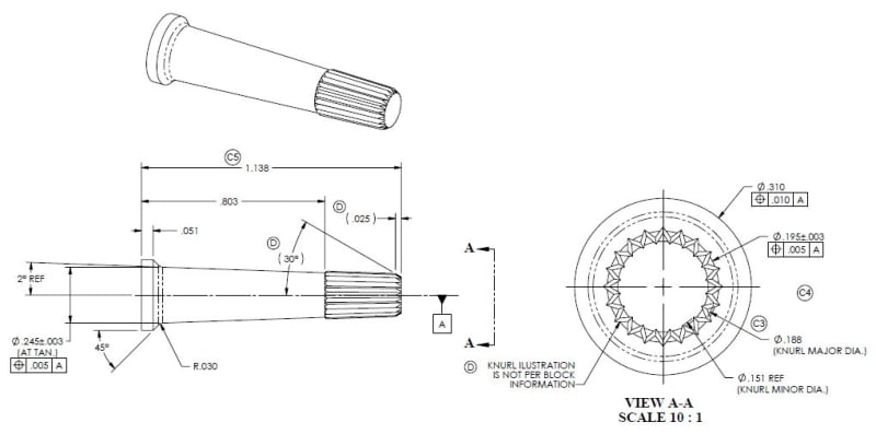
Its a simple part per ASME Y14.5, and I know its not allowed to label a center line as a datum feature, so I am confused on how to setup the part for inspection, what will you do? Its not a good print, any comments are welcome.

Knurling_tcht2y.jpg


Season
 
Replies continue below

Recommended for you

Since no feature is given the datum symbol, then it's game-over. Nothing to do besides kick it back.
 
Right -- we'd have to know the exact function of the part to answer the question.

John-Paul Belanger
Certified Sr. GD&T Professional
Geometric Learning Systems
 
If you are the Checker, how will you correct it?

Season
 
Any checker I've worked with would have put a red X over the datum symbol and write "Identify the datum feature correctly" before dropping it back on my desk.
 
Ask to have the position tolerance cleaned up too.

Cheers, hatsegal
"Think first"
 
Looking closer - the position tolerances are on the diameters, but don't have the diameter modifier on their tolerances.

A lot of checkers would not mark that up until the datum symbol was fixed, to make a second round of red marks.
 
There should be red marks all over this print. Seems to me that unless specified on another view, the actual tapered portion is wholly uncontrolled with the only angular dimension attached being a reference dimension? And theres a position control attached to a point of tangency (AT TAN?)?

I don't envy you. The print doesn't show it, but is the part perhaps drilled for centers?

Ditto what 3DDave/JP said, I would go back to the customer and ask them what in the heck they were thinking. Theres no way to be sure what datum feature A should be in order to derive the designated axis - one of the main reasons why this practice is prohibited in Y14.5. They need to update the print with some semblance of proper notation.
 
All the comments are fair so far, but an important point about the most significant issue with the drawing is that the symbol is not a "datum symbol". It's a datum feature symbol. This is one of those cases where terminology is a key thing. After the datum feature label is moved to a datum feature, then the many other issues can be addressed. For instance, at what axial location do the .151, .188, and .195 diameter tolerances apply? Then maybe fix the lack of diameter symbols and mixing of "REF" and "()".

Dean
 
Dean,
It is certainly not a datum feature label either. How can one move a datum feature symbol to a datum feature? A feature is not a datum feature until after the symbol indicating that status is applied.

 
3DDave,

It is a datum feature symbol here or there.

It is a datum feature symbol anywhere.

:)

Once a given feature has been selected as a datum feature, a datum feature symbol is placed properly so that others will know what we have decided. Y14.5 clearly defines the symbol a datum feature symbol. It does not call it a datum symbol anywhere except for a mistake in the title of Figure C-1.

The reason it is important to call it by the correct name, datum feature symbol, it to reduce the likelihood of using it incorrectly, by instead applying it to a datum, as it was in the drawing that SeasonLee points out as wrong.

By what reasoning would one call something that is applied to datum features to indicate them as such, and that is prohibited from being applied to datums, a "datum symbol"?

Dean
 
Dean Watts said:
The reason it is important to call it by the correct name, datum feature symbol, it to reduce the likelihood of using it incorrectly, by instead applying it to a datum, as it was in the drawing that SeasonLee points out as wrong.

Dean,

Is it the same reasoning on why datum feature shift is preferred instead of datum shift ?

If yes, what about displacement name used for the same nomenclature? Are there any naming change / added clarification from 2009 to 2018?
 
Hi Aniiben,

Uh oh. My opinion on shift terminology is not aligned well with the wording in any version of Y14.5. When shift is present, the entire part may shift relative to the entire datum reference frame, so my preference is to call it "Datum reference frame shift".

If only a portion of the part, a datum feature, was shifting, then I would be OK with calling it "datum feature shift". That is not what is happening though.

Getting agreement on whether a datum reference frame exists with less than 6 degrees of freedom constrained (with just one or two datum features referenced) would be a good first step towards getting to what I believe would be better "shift" terminology. Those who look at the situation as a DRF only existing if it is fully constrained are the ones who want to call an entire part shifting relative to an entire DRF "datum feature shift". I think it makes more sense to define a DRF as a coordinate system that is wholly or partially constrained by datums.

Thoughts and darts?

Dean
 
If only a portion of the part, a datum feature, was shifting, then I would be OK with calling it "datum feature shift". That is not what is happening though.

It certainly can be though, imagine a part with a planar face datum feature A and central bore (perpendicular to A) designated datum feature B and 2x holes on either side with a 2X 0@MMC position tolerance to |A|B(M)| *. If the 2X bores both come in at MMC the only feature which is able to shift wrt its simulator is the datum feature. Of course I don't mean this as actual movement (ie: the part cannot move/shift once placed on the gauge) but as in the possible places which datum feature B can be produced at.

I think "datum feature shift" describes best the mechanism which allows the shift to happen - namely disconnecting (or loosening) the relationship between the datum feature and its simulator. Of course in most non-theoretical parts this allows the behavior you describe with shift relative to the datum reference frame, however this is a result not the underlying cause.

*Edit - changed B to MMB
 
Chez311,

I might be missing something about what you're saying, but did you mean the position tolerance would be to |A|B(M)|?

Even if you did, if the 2X bores were at their virtual condition, as I think you're describing, wouldn't they lock out against their gage elements, preventing any shift? Datum feature B being at various non-worst case places in this situation does not fit the definition of shift from my point of view.

So, I still think any time there is shift the whole part is shifting relative to the datum reference frame.

Dean
 
Sorry, Dean, both here and there you call them datum feature LABELS. And then went out of your way to terminology police me when the symbol wasn't attached to any feature at all, so it was just a symbol.

aniiben, It should be "theoretical datum feature simulator shift" to keep up with the fully qualified terminology the terminology police so enjoy.
 
Dean,

Yes you are correct - I meant |A|B(M)|, critical error on my part. I have edited the post to reflect this.

Even if you did, if the 2X bores were at their virtual condition, as I think you're describing, wouldn't they lock out against their gage elements, preventing any shift? Datum feature B being at various non-worst case places in this situation does not fit the definition of shift from my point of view.

It would indeed "lock out". Notice I had said that it wouldn't result in actual movement as the part would not be able to physically move/shift once on the gauge. I'm also not so sure about your labeling this as "non-worst case" - I believe if the datum feature was produced at LMC and shifted off-axis by the maximum amount allowed until it touches on one side would be one of the potential worst case positions for datum feature B relative to its simulator.

I see nothing in the definition that requires shift to be physical movement of the part. Would you not say the below datum feature (central bore) has shifted in relation to its simulator? If not, what term would you prefer to describe this behavior and what advantage do you see in differentiating it? It seems to me this behavior is sufficiently covered by the definition and concept of datum feature shift as contained within the standard - notice the definition includes only the relationship between the datum feature and its simulator. Additionally one still benefits from datum feature shift as the same part would fail if referenced at RMB.

shiftMMB_px79s2.jpg
 
Good Morning 3DDave,

No need to get indignant. We're all here commenting based on technical concerns. Terminology issues that contribute to incorrect application of GD&T, such as datum feature symbols (Y14.5 does not call them labels) being called datum symbols, as those symbols incorrectly end up on datums instead of datum features far too often, are worth mentioning. GD&T is done incorrectly far too often, as you know. Many of your posts on this forum make it clear that you have a lot of experience and many of the things you say are very insightful. I intended no offense. My only interest is having this subject clarified and used as efficiently as possible. Regarding the terminology for shift, I think it could be described in the theoretical or physical/real sense. Either is valid. I tend to align with your words, by the way, in preferring to say datum feature simulator in place of true geometric counterpart.

I think the word "True" is troublesome, since in non-English speaking regions it may be interpreted as real/correct/actual, instead of how Y14.5 uses it, to mean "Theoretically exact". To speak of terminology more, I think "True" and "Basic" should be replaced with "Theoretically" or "Theoretically exact", depending upon the particular use. Also, all of our boundary names, inner, outer, worst-case, virtual, and resultant should be replaced in all places with maximum material boundary (MMB) or least material boundary (LMB). I also think "TGC" and "Datum feature simulator" should be replaced with "Theoretical geometric counterpart" and "Physical geometric counterpart" (credit to Mark Foster, since these were the outcome of a brainstorming discussion he and I recently had about these terms), since the word "true" is troublesome and I agree with those who say word "simulator" isn't the best term as it is being used. It would then follow that we could use the terms "Theoretical datum" and "Physical datum" (in place of "Datum" and "Simulated datum") I think these changes would create a simpler, "safer", more logical, and more clear set of terms. All "pie in the sky" thoughts though, since standards are hard and slow to change.

Good Morning chez311,

I think you and I are aligned on how shift is supposed to work and the overall effect. Your example picture is helpful too. If I understand correctly, you're saying the part didn't shift, but instead the datum feature has shifted wrt what would be its RMB relationship to the datum. I am saying that the part would (at least conceptually) start with the datum feature at the location and orientation that the RMB (default) datum feature simulator set would put it, then the part would shift to the location you show in order to satisfy the size and position at (M) tolerances on the 2X holes. You're point is valid, I believe. We just have differing starting points for the part wrt to the DRF. Do you also see the difference between your description and mine in the this way?

Dean
 
Hi All,

FWIW, I support Dean's terminology policing. He and I both know from bitter experience (and the teachings of Bill T.) that strict attention to the details of terminology is essential where GD&T is concerned. We've been in many committee discussions where the source of a misunderstanding turned out to be terminology. I would go as far as to say that many of the difficult aspects of GD&T are at least partly caused by the confusing/counterintuitive/inconsistent/conflicting use of terminology in the standard itself. Don't get me started on the whole "datum plane" thing. ;^)

Regarding the term "datum feature shift" versus "datum shift", I don't have a big preference either way. The only thing that matters is that there can be relative movement between the datum feature (and thus the rest of the actual part) and the TGC (and thus the datums and the DRF). It doesn't matter if you think of it as the part moving relative to the gage, or as the gage moving relative to the part. You can find examples of both of these descriptions in Y14.5.

I have much more of an issue with the confusing way that Y14.5 defines and describes the term "datum feature shift/displacement":

"MMB or LMB modifiers applied to the datum feature reference allow the datum feature to shift/displace from the boundary established by the true geometric counterpart in an amount that is equal to the difference between the applicable (unrelated or related) AME for MMB, actual minimum material envelope for LMB, or surface of the feature and the true geometric counterpart."

I agree that this definition implies that the datum feature starts out at the location it would be at if the reference was RMB, and then shifts/displaces from there. But then it goes on to say that the amount of shift is the difference between the AME and MMB - shouldn't this be half of the difference? I would say that trying to quantify the amount of shift is ill-advised in the first place, because it really only works for the special case of a single datum feature such as datum feature B in chez311's sketch. In almost every real case, datum feature shift is a complicated mixture of rotational shift and translational shift. The "amount" varies depending on the direction.

The figure that illustrates datum feature shift/displacement (Fig. 4-26 in 2009, Fig. 7-18 in 2018) is one of my "pet peeve" figures. It has a square 4-hole pattern referenced as a secondary datum feature at MMB.
-it shows "Datum Axis B". According to Y14.5's own theory, the datum for this type of datum feature (linear extruded shape) would be an axis and center plane, not an axis. This is just so incredibly misleading, because a datum axis would leave one rotational degree of freedom open.
-the figure shows what looks like an "actual" coordinate system with planes and an origin, that was derived from the as-produced datum feature. It is not generally possible to uniquely define this actual coordinate system, it is only possible because the as-produced datum feature in the figure has equally sized holes at true position relative to each other.
-the figure shows "one possible displacement of the hole pattern with respect to the datum reference frame" and points to an X direction gap between the actual coodinate plane and the plane of the datum reference frame. The displacement is actually a mixture of X translation, Y translation, and rotation.

Evan Janeshewski

Axymetrix Quality Engineering Inc.
 
Status
Not open for further replies.

Part and Inventory Search

Sponsor