In cases where my secondary and tertiary datums are features of size, is the implied 90° angle of those features with ±1° angular tolerance from the title block enough to satisfy the datum orientation control requirements of 4.9(b)/4.9(c)?
Using Y14.5-2009, Section 4.9
"Datum features shall be controlled directly by applying appropriate geometric tolerances or indirectly by dimensions such as the size of a primary datum feature of size.
(a)form of the primary datum feature(s) and/or the location between features in a pattern used to establish the primary datum.
(b)secondary datum features’ orientation and/or location as applicable, to higher precedence datums.
(c)tertiary datum features’ orientation and/or location to higher precedence datums as applicable."
As an example, I have a small bent sheet metal part with two equal flanges, similar to a C-channel shape. It has a hole on center face that will be located by the datums. I have the center face as Datum A, the midplane of the flange to flange distance as Datum B, and the midplane of the width as Datum C. To qualify the datums using FCFs, you'd want flatness on A, then a perpendicular on 2.00 dim referencing Datum A, then a perpendicular on .50 dim referencing Datum A and B. But is it allowed to only have flatness on Datum A and no perpendicular controls because the flanges already have to stay within ±1° from title block tolerances? See image
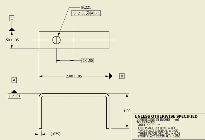
I understand that Rule #1 applies to features of size and only control form, so the direct tolerance alone would not satisfy the orientation requirements of 4.9(b). This would allow the flanges to end up like a parallelogram/trapezoid. But Rule #1 along with the implied 90° angle with ±1° title block tolerance should create limits for the part. I also understand that ±1° is deceptively loose and could cause issues with larger parts, but with short flanges (this example has 1" long flanges), the amount of variation will be small.
This question is mainly because the part doesn't need tight tolerances so adding perpendicular controls feels redundant at times.
I've done some searching on this forum and found threads that were very similar, but never seemed to directly answered my question.
Link
Link
Thanks
Using Y14.5-2009, Section 4.9
"Datum features shall be controlled directly by applying appropriate geometric tolerances or indirectly by dimensions such as the size of a primary datum feature of size.
(a)form of the primary datum feature(s) and/or the location between features in a pattern used to establish the primary datum.
(b)secondary datum features’ orientation and/or location as applicable, to higher precedence datums.
(c)tertiary datum features’ orientation and/or location to higher precedence datums as applicable."
As an example, I have a small bent sheet metal part with two equal flanges, similar to a C-channel shape. It has a hole on center face that will be located by the datums. I have the center face as Datum A, the midplane of the flange to flange distance as Datum B, and the midplane of the width as Datum C. To qualify the datums using FCFs, you'd want flatness on A, then a perpendicular on 2.00 dim referencing Datum A, then a perpendicular on .50 dim referencing Datum A and B. But is it allowed to only have flatness on Datum A and no perpendicular controls because the flanges already have to stay within ±1° from title block tolerances? See image
I understand that Rule #1 applies to features of size and only control form, so the direct tolerance alone would not satisfy the orientation requirements of 4.9(b). This would allow the flanges to end up like a parallelogram/trapezoid. But Rule #1 along with the implied 90° angle with ±1° title block tolerance should create limits for the part. I also understand that ±1° is deceptively loose and could cause issues with larger parts, but with short flanges (this example has 1" long flanges), the amount of variation will be small.
This question is mainly because the part doesn't need tight tolerances so adding perpendicular controls feels redundant at times.
I've done some searching on this forum and found threads that were very similar, but never seemed to directly answered my question.
Link
Link
Thanks