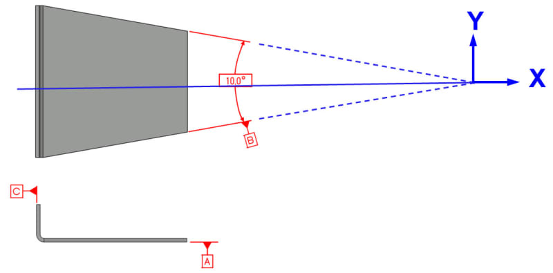
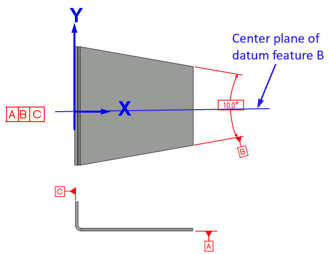
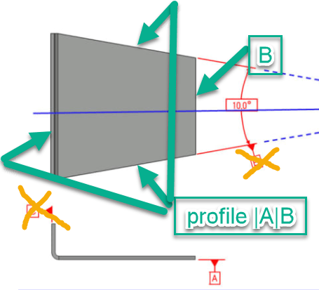
Eng-Tips is the largest engineering community on the Internet

Intelligent Work Forums for Engineering Professionals

  • Congratulations waross on being selected by the Tek-Tips community for having the most helpful posts in the forums last week. Way to Go!

Datum on angular slab centerline 2

Status
Not open for further replies.
Replies continue below

Recommended for you

I think in theory it is. In this case you don't need C (tertiary) because B is able to arrest all remaining degrees of freedom.
You put a profile feature control frame wrt A, with two leader lines pointed to both surfaces, and attache datum feature symbol B to the profile FCF.
 
greenimi said:
because B is able to arrest all remaining degrees of freedom.

From what I understood, the apex(as shown on the fig below) will be the datum point of this part, this is almost same as the conical case (e) on Figure 7-3 2018 version. Am I right here?
2021-05-24_072341_uffobh.jpg


Season
 
Standard allows us to use any geometry as a datum.

Question is, how to identify that geometry correctly.

With all necessary precautions the final DRF may look like this:

Part1_ckl648.jpg


The general idea is similar to, for example, Y14.5-2009 Fig. 4-44, but since datum is formed by 2 separate non-coplanar surfaces, each surface is identified individually.

Little edit: 30 deg angle better be basic.

"For every expert there is an equal and opposite expert"
Arthur C. Clarke Profiles of the future
 
CH

Thanks for your input and figure, may I understand this way: the datum point will be different(as shown below) if no profile FCF callout as you recommended.
2021-05-24_095131_hqt42z.jpg


Season
 
@ SeasonLee:

You can have datum point anywhere you want.

My example was just in agreement with greenimi note that tertiary datum may not be necessary.

You can force your datum where it works for you. I referenced Y14.5-2009 Fig. 4-44; the very next Fig. 4-45 shows how to use customized datum frame to place your datums the way you need.

"For every expert there is an equal and opposite expert"
Arthur C. Clarke Profiles of the future

 
Yes, that's the way I see it:

2 flat surfaces on the angle to each other give you center plane:

Capture_kknfpp.png


And, like I mentioned, you can also add your own datum plane and create your own DRF


"For every expert there is an equal and opposite expert"
Arthur C. Clarke Profiles of the future
 
Thanks, CH.

I think the OP's secondary datum feature B is also a center plane callout, I am anxious to know what is the differences between them.

Season
 
It's curious that the tapered example "complex" feature only produces one center plane; the planes tangent to the curved faces should also create a center plane, otherwise that axis could not be determined. It's at the intersection of two center planes. It raises the question of what it means on a manufactured part that those planes don't necessarily intersect at a single point.
 
Here's a variation that locks 6 degrees of freedom - the top and bottom surfaces aren't necessarily parallel to each other or normal to the axis. The axis is arbitrarily oriented relative to the 3 main faces. It does not appear to fit within the suggested possible feature types in ASME Y14.5-2009, figure 4-3.

complex_fig_4-3_zcqnp4.png
 
If you use Profile to describe the non-parallel surfaces you open the door to using MMB modifier on that datum in subsequent FCFs. I'm not sure is this is answering the OP's second question or not.
 
OK maybe I didn't give up...

This will help prevent having the inspector invoke an ancient curse upon your family. It will also get the result you need.

2021-05-26_9-16-54_yqmwq3.png
 
Status
Not open for further replies.
Back
Top