Continue to Site

Eng-Tips is the largest engineering community on the Internet

Intelligent Work Forums for Engineering Professionals

  • Congratulations waross on being selected by the Eng-Tips community for having the most helpful posts in the forums last week. Way to Go!

Datum Reference 4

Status
Not open for further replies.

AlexFH

Mechanical
Apr 29, 2024
3
Hi,

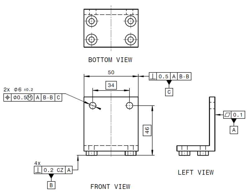
In this case, Datum B is a group of four faces. Should I use B or B-B?

I have always used B in cases where I use the CZ modifier, and in my mind B-B should not be necessary to use since the four surfaces shall be interpreted as one surface already.
But recently one of my colleague attended a GPS training course and the trainer told my colleague to use B-B. So I'm a bit confused, because I cannot find any examples of this in ISO. I have used "B-B" for e.g. hole patterns. So if anyone can point me to where I can find what I'm looking for in the standard, I would appreciate it very much.

I'm working with ISO GPS, but I assume there are some similarity between ISO and ASME in this regard.

a)
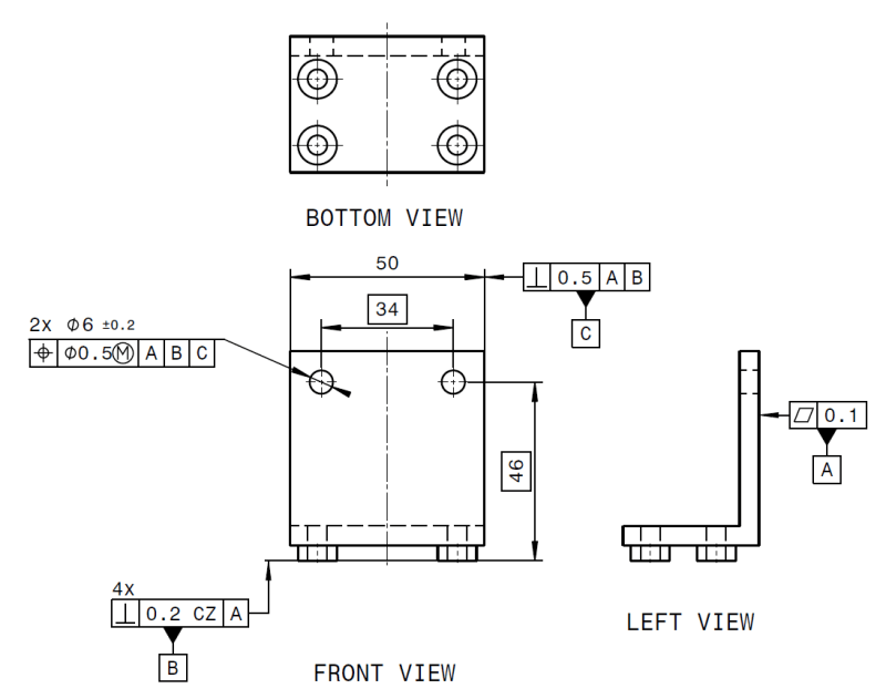
Datum_B_image_rswf9b.png


b)
Datum_B-B_image_q7crv0.png
 
Replies continue below

Recommended for you

Well, CT is most commonly used when several features of size are to be considered as one.
Imagine a pipe with a groove in it (all coaxial) You want the diameter before AND after the groove to be evaluated as one diameter, not two separate ones as is the default in ISO if you do not state otherwise.

UF on the other hand is most often used as in the example you provide above; these several sub sections of a cylinder (that are not in themselves features of size)that are divided by splines are together to be interpreted as one feature of size.

CT> most often coaxial

UF>most often coplanar
 
Burunduk

I guess the answer of your question is depending how you interpret the Note 2 and specially "However, it is not intended that a united feature can be used to define something that is by nature several separate features."


"I am quoting para. 3.9 in ISO 1101:2017 below to support the last statement:
"Note 2 to entry: The definition of a united feature is intentionally very broad to avoid excluding any useful applications. However, it is not intended that a united feature can be used to define something that is by nature several separate features. For example, building a united feature from two parallel, non-coaxial cylindrical
features, or two parallel, non-coaxial rectangular tubes (each built from two perpendicular pairs of parallel planes) is not an intended use.""


In your original question regarding CT:
Are those two coaxial features BY NATURE (in my 3D CAD annotated model) separate features? Or they are a single stand alone feature?
One might say YES (They are separate features) ......someone else might say NO (is a single feature and the slot had been added later)

 
MaxSka9,
Your explanation makes sense, thank you very much.
Personally, it seems to me, that in this case, ISO could do with one modifier less.
In ASME Y14.5 there is the Continuous Feature symbol (put inside an elongated hexagon frame next to a tolerance callout), which I believe would manage both cases; the fully cylindrical pipe segments interrupted by circumferential grooves as you mentioned, and the spline shaft with the partial arc segments.

greenimi,
I agree, there seems to be some room left for interpretation.

It also seems that two different standards define the two modifiers, UF is defined in ISO 1101:2017, and CT is defined in another ISO standard.
 
UF can always be used instead of CT, but not the other way around. There's plenty of these refinements in the ISO standards and I think their value is questionable.
 
Thank you Ryan,
So, would it be correct to conclude that CT is actually a special case of UF, intended for coaxial/centered features of size with the same size requirement?
 
ISO 5459:2011, Annex D.3 reminds us that is a former practice to indicate a common datum established from a group of features with and indication of single datum.
I would say that this is still very common, I see it often in both older and more recent drawings.

As already mentioned above, ISO 5459:2011 Rule 7, section 7.4.2.7 show indication of a common datum as "A-A" in the tolerance frame.
5459 show examples secondary common datums for examples of group of holes, but lack good examples showing co-planar common datum for examples of 4x ref A CZ that would be indicated as A-A in the primary datum tolerance frame.

I agree it is not a pretty way to have your tolerance frame in the odd case where you end up with "A-A" "B-B" "C-C".
 
Status
Not open for further replies.

Part and Inventory Search

Sponsor