Continue to Site

Eng-Tips is the largest engineering community on the Internet

Intelligent Work Forums for Engineering Professionals

  • Congratulations cowski on being selected by the Eng-Tips community for having the most helpful posts in the forums last week. Way to Go!

Datum Shift Example

Status
Not open for further replies.

pyromech

Mechanical
Jul 30, 2008
39
Folks

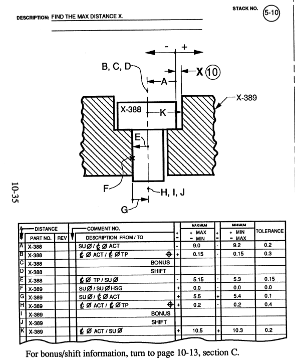
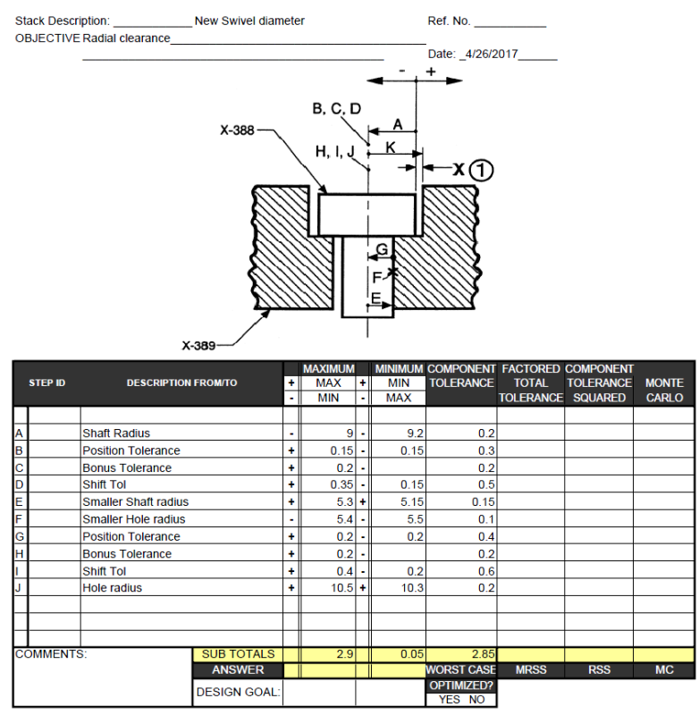
I am reading Alex Krulikowski workbook, Exercise 5-51 and there is a mistake on Line J, datum shift. It should be 0.2;
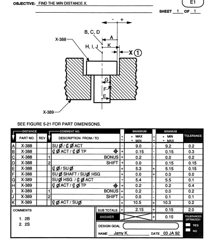
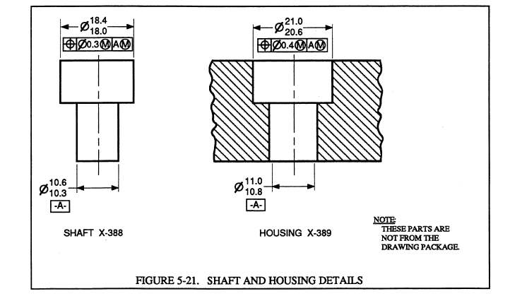
stack_lcxawc.png

stack1_pcsvtr.png


VC=10.3-0.2=10.1
MMC-VC= 10.3-10.1=0.2

What do you think? I get annoyed when he mentions that for assembly stacks, it requires two different stacks where the components are assembled at their extremes for what you looking for. But for most cases, you can use the same stack specially in this case??
So what would be the Max Distance X? My results are attached..
my-result_wvilen.png


thanks
 
Replies continue below

Recommended for you

Alex's answer is correct. It looks like your calculation of shift is based on the VC and MMC of the top part of that housing. But datum shift comes from the datum feature, which in the housing is the lower diameter, labeled as datum feature A. Thus the shift is the difference in that size (11.0 - 10.8) then cut in half for a radial-only shift.

The idea of requiring two different stacks where the components are assembled at their extremes is often essential, because doing two stacks accounts for the play or looseness between parts in an assembly. Notice in his answer key that the 2.15 sub-total is not counted as an answer, because the "stack path" is based on the assumption that the parts are always touching at that "X" contact point to yield a minimum-column answer.
In some cases you might not need to do two stacks: If you know that the parts will be permanently glued or welded at a certain contact point.

John-Paul Belanger
Certified Sr. GD&T Professional
Geometric Learning Systems
 
You are saying datum shifts approach is different in parts and assemblies. The Bonus/Shift Chart is the same except the equation is reversed for shaft.


bonus_brsavh.png

bonus1_arf2af.png
 
The datum shift approach isn't different in parts vs. assemblies. But parts and assemblies differ in that a part stack needs only one spreadsheet calculation while an assembly stack (usually) requires two spreadsheets.


John-Paul Belanger
Certified Sr. GD&T Professional
Geometric Learning Systems
 
Thanks. Here is the spreadsheet for max distance where he could easily merge it into one.

stack2_nodbwy.png


But in any case, what happens if there are two datum features modifiers, on B & C. Do you add them up? add whatever size difference it is. say: (11.0-10.8)/2 + (25-23.5)/2.

stack3_csxqec.png
 
No -- although there might be datum shift on both B and C, the shifts don't get added together because each datum controls different "degrees of freedom."

Imagine if datum B has some looseness: It might be a hole that allows looseness in all directions. But when it comes to datum C, its shift tolerance acts in a different direction (such as rotation-only). So datum shifts in the same callout are never added together. You'd only use the shift which correlates to the direction of your stack's path.

John-Paul Belanger
Certified Sr. GD&T Professional
Geometric Learning Systems
 
In the first example for Minimum distance:

The maximum shift of the LMC shaft in the LMC hole is:
+Dia 11.0 (LMC hole)
-Dia 10.3 (LMC shaft)
=Dia 0.7 diametral shift between datum features.

The maximum condition of the cap on the shaft is:
+Dia 18.4 (MMC of cap)
+Dia 0.3 (position tolerance at MMC)
+Dia 0.3 (datum shift tolerance between MMC and LMC of datum feature)
=Dia 19.0 Virtual condition of cap relative to LMC datum feature

The minimum condition of the cbore is
+Dia 20.6 (MMC of the cbore)
-Dia 0.4 (position tolerance at MMC)
-Dia 0.2 (datum shift tolerance between MMC and LMC of datum feature)
=Dia 20.0 Virtual condition of cbore relative to LMC datum feature

Gap is:
{
+Dia 20.0 VC cbore
-Dia 19.0 VC cap
-Dia 0.7 Datum shift
}/2
=Radius 0.15

Much easier to trace by leaving the division by 2 to the end.
 
pyromech,

I would like to offer some thoughts about some of the statements you made:

1. Just to back up J-P, there is no mistake on line J in the original stack for MIN value.

2. For MAX value, the answer would be 2.85 (see attachment below):

3. The idea of having two different stacks for MIN and MAX value of a gap in assembly is correct, although it does not mean that it is impossible to calculate both values in a single stack. One should just be aware that even if the calculated worst-case (W-C) values will be the same in both methods (two stacks vs. single stack), there will be a difference in RSS numbers. The difference may be important, thus not acceptable, in certain situations.

Below you will find a short study showing what I mean. I used the same assembly as Alex K. and the same tolerance values, but to simplify things I removed all (M) modifiers from the features control frames involved in the calculations (in other words, I crudely got rid of all bonuses and datum shifts).

4. And finally, the most important thing, in my opinion. There is a fundamental flaw/mistake in the entire discussed stack. It assumes that everything is perfectly perpendicular to each other. For example, just imagine that the mating face in the housing is out-of-square relative to the axis of the thru hole. This will immediately give different value for MIN gap X.

The problem is that the way the parts have been defined on their drawings does not mimic the way they really function/work in the assembly. To me both position callouts should refer to mating face as primary datum feature, and both datum feature cylinders should merely be secondary and controlled with perpendicularity tolerances to the primary face. With both perpendicularity tolerances set at 0 at MMC, nothing would have to be changed in the stacks for MIN and MAX values, regardless of chosen method.
 
Status
Not open for further replies.

Part and Inventory Search

Sponsor