Continue to Site

Eng-Tips is the largest engineering community on the Internet

Intelligent Work Forums for Engineering Professionals

  • Congratulations KootK on being selected by the Eng-Tips community for having the most helpful posts in the forums last week. Way to Go!

Datum shift 2

Status
Not open for further replies.

Sa-Ro

Industrial
Jul 15, 2019
273
Hi

Refer my attachment.

What is use of datum shift?

Everyone defining, we can adjust the datum feature during inspection to make the corresponding feature approved.

My doubt:
To ensure the coaxiality of dia 10, the gauge ID will be V.C of 10.2.

As long as the dia 10 feature manufactured within dia 0.1 position tolerance, is there any use with datum shift?

(or)

If the feature is out of tolerance and by utilizing this datum shift we can make this feature approved?
 
 https://files.engineering.com/getfile.aspx?folder=d328a938-94ca-4b7d-85d7-1062f9c4c127&file=IMG_20200605_210150.jpg
Replies continue below

Recommended for you

Short answer: yes, you can use in this case your available datum displacement "to make this feature approved". But ONLY in this case because there is ONLY one feature controlled (coaxial) relative to one datum axis. DO NOT extent this "allowance" or this special case to anything else more than that you are showing on your attached hand sketch.
I assume you are using ASME.

 
Hi Greenimi

Thank you.

I am trying to understand with single feature.

So the above example is attached.

Now the actual topic is attached from ASME Y14.5:2018.

In this part, as long as the four hole pattern answering to V.C of dia 8.5 gauge (4 no's) with datum feature RFS condition, datum shift will not required.

Datum shift will be helpful when the four hole pattern is not able to answer with RFS condition.

Shall I consider this datum shift will be useful for deviation of the part.
 
 https://files.engineering.com/getfile.aspx?folder=d7da6554-24b1-4a2d-95a7-dab1a2c1ee66&file=Screenshot_2020-06-06-00-06-40-791_cn.wps.xiaomi.abroad.lite.jpg
Sa-Ro said:
In this part, as long as the four hole pattern answering to V.C of dia 8.5 gauge (4 no's) with datum feature RFS condition, datum shift will not required.
Datum shift will be helpful when the four hole pattern is not able to answer with RFS condition

I think you are correct on the above statement.

 
Ok. Let us assume we are utilizing datum shift.

The above example was cylindrical feature. Hence if the datum is produced at dia 39, the four hole pattern can dislocate within dia 1.5.

Refer my attachment.

Image from ASME Y14.5:2018

In this square feature, assume the part is produced at 35.5 (horizontal) X 36 (vertical).

Now how much the centre hole dia 22 can dislocate apart from position tolerance of dia 0.25.

Do the dia 22 bore can dislocate 0.75 (0.25 + 0.5) in horizontal direction?

I would like to inspect without hard gauge.
 
 https://files.engineering.com/getfile.aspx?folder=4321d8f6-f810-4012-a25e-f9bd124160c5&file=Screenshot_2020-06-06-06-29-18-888_cn.wps.xiaomi.abroad.lite.jpg
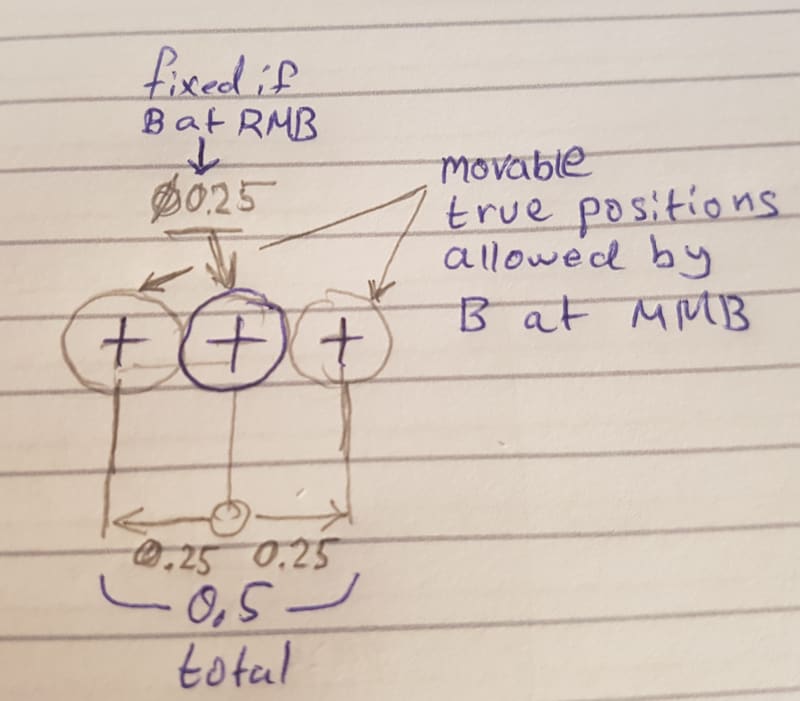
Suppose that the 35.5 horizontal width was also produced with perfect orientation to A, the datum shift would be 0.5, which is the difference between the datum feature's MMB and it's related actual mating envelope. The hole can not "dislocate apart from position tolerance of dia 0.25.", it can be "movable" within 0.5 when best fitted into the 0.25 (At MMC) tolerance zone.
 
Burunduk

Sorry, I am failed to understand.

If the hole dia 22 is produced within dia 0.25 position tolerance, that feature will be approved in RFS itself.

Then what is the need for datum shift.

Generally we used to consider the counter part and provide tolerance for both parts to assemble in all condition within tolerance range.

If possible, can you explain with drawing?
 
Sa-Ro, the datum shift does give you additional allowance for the part to pass, compared to the RFS RMB case. It's just that I would not describe it as allowing the feature deviate from the 0.25 tolerance zone - that kind of thing leads to wrong conclusions especially where features in a pattern are considered. You say that you want to inspect without a hard gage. I'm no inspection guy but I think the most suitable way to describe datum shift where the part is not moved around in a fixture is as follows: let's say the 22 diameter bore is produced at MMC, and the related actual mating envelopes of the widths datum features are as you say 35.5 (horizontal) and 36 (vertical). Imagine you have a "sight" (as the aiming device of a weapon) of diameter 0.25. The center axis of your bore must fall within that sight. In the RFS RMB case, the sight is fixed in the origin of your datum reference frame and you can't "aim" with it. In the MMB case, because the difference between the MMB of datum feature B and it's related actual mating envelope is 0.5, it means you can move the 0.25 diameter "sight" left and right total distance of 0.5 to "aim" at the axis of the bore and make it pass.
 
Understood 50%.

For better understanding with visual.

Ref:
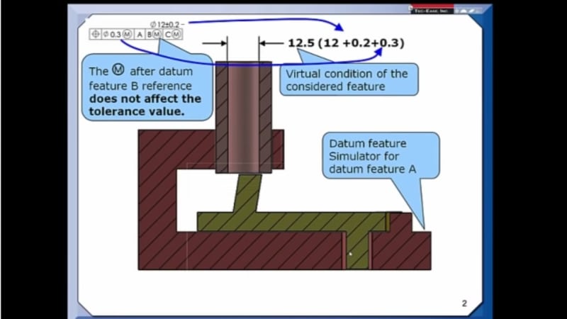
Tec-ease video on datum shift.

Assume considered feature is produced at dia 12.2, tilted within dia 0.3. since the feature is tilted 0.3, feature produced location is assumed 60.

Hence the related actual mating envelop is 12.34.

Refer attachment.

V.C is dia 12.5. Now this feature is approved with datum RMB.

But the video shows, datum shift required. How?
 
Sa-Ro,
I haven't watched the youtube video yet.
The sketch in your last attachment is not accurate. I will upload a correct one soon.

The total "traverse" distance is 0.5. This is for the specific condition where RAME of datum feature B is 35.5, so that the calculation is MMB-RAME=36-35.5=0.5.

Edit - the correct image is in the attachment

 
Ok. So the datum shift will allow the tolerance zone to move (without affecting the location dimension) within datum shift allowance.

Example "U" shaped circular feature. Distance between two circle centre line is fixed. As a hole "U" shape, it can move to assemble into counter part. Right?

But, Generally we used to consider the counter part and provide tolerance for both parts to assemble in all condition (datum at MMC and feature at MMC) within tolerance range.

Then what is the necessity to move the tolerance zone as datum shift?
 
Sa-Ro,
From some reason I could not edit my previous post to attach the correct image. There was a mistake in the one I initially posted too. Here is the correct image. Hope this helps you to visualize datum shift.
20200606_181752_nlx40x.jpg
 
Thank you. I am well understood the datum shift from your image.

My question is:

Generally we used to consider the counter part and provide tolerance for both parts to assemble in all condition (datum at MMC and feature at MMC) within tolerance range.

Then what is the necessity to move the tolerance zone as datum shift?
 
Sa-Ro said:
Then what is the necessity to move the tolerance zone as datum shift?

To allow the part displace relative to the datum reference frame just as it displaces during assembly with the mating part when there is available clearance for some movement. As a result, additional allowance is available as features can dislocate (as a single feature or as an entire pattern with all its features simultaneously) from their fixed (at RMB) true position(s). I showed the displacement of the part relative to the DRF as mobility of the tolerance zone because maybe this may help to understand it in the context of inspection without a fixture as you asked, when the part is not actually moved anywhere physically.

Also, notice the terminology: for datum features the M modifier is MMB, overriding RMB (for "considered" features the modifier means MMC overriding RFS).
 
OK. Now I am getting more clarity.

The tolerance zone can shift as much as datum shift is available which means the location dimension can vary.
 
"location dimension can vary."
Only in comparison to RMB. The tolerance for location around true position does not enlarge. The true position itself can "shift" relative to the part, or another way to way to look at it is the part can shift relative to the theoretical datums.
 
Thank you.

Thank you.

I am clear about datum shift.
 
Sa-Ro,
You're welcome. Are you also clear about the Tec-Ease video?
I'm not sure I understood your calculation of VC=12.34.
Anyway, the point of the video was that the considered feature was produced somewhat tilted or dislocated or both in a way that it doesn't fit in its virtual condition sleeve gage located exactly at 60 from datum B as shown here:
Screenshot_20200606-211529_YouTube_n03ndn.jpg

However because datum feature B was produced with its related AME smaller than the MMB gage, it allowed the part to move the amount of available datum shift relative to the datum axis to fit within the gage. But that doesn't mean the tolerance for the location of the considered feature got any larger because of the MMB modifier. If datum feature B was produced at a RAME size equal to the MMB (12.3 as in your sketch), datum shift would not be available and the part wouldn't pass in that condition.

Edit: to explain in other words why datum shift doesn't allow "bonus" or additional tolerance: you can't enlarge the 12.5 V.C. sleeve gage just because datum B's RAME was produced less than 12.3.
 
I am not sure about Tec-ease video.

Because the feature is tilted within dia 0.3 and located at 60. VC of that feature is Dia 12.5.

I have drawn a sketch to tilt the feature to find out the RAME - extenal (12.34).

Hence 12.34 can be easily pass thru 12.5 with RMB - feature approved.

But they showed, part will not pass thru with RMB.

The part was designed such that the datum B at MMB, feature at MMC, TP at dia 0.3 will pass thru the VC of 12.5.

My doubt was started from this video only.

Anyway I understood the datum shift (simply, allowance to deviate in location tolerance) concept from your reply.
 
Status
Not open for further replies.

Part and Inventory Search

Sponsor