Continue to Site

Eng-Tips is the largest engineering community on the Internet

Intelligent Work Forums for Engineering Professionals

  • Congratulations KootK on being selected by the Eng-Tips community for having the most helpful posts in the forums last week. Way to Go!

Datum shift 2

Status
Not open for further replies.

Sa-Ro

Industrial
Jul 15, 2019
273
Hi

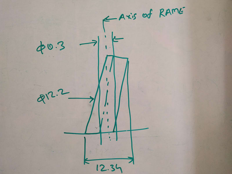
Refer my attachment.

What is use of datum shift?

Everyone defining, we can adjust the datum feature during inspection to make the corresponding feature approved.

My doubt:
To ensure the coaxiality of dia 10, the gauge ID will be V.C of 10.2.

As long as the dia 10 feature manufactured within dia 0.1 position tolerance, is there any use with datum shift?

(or)

If the feature is out of tolerance and by utilizing this datum shift we can make this feature approved?
 
 https://files.engineering.com/getfile.aspx?folder=d328a938-94ca-4b7d-85d7-1062f9c4c127&file=IMG_20200605_210150.jpg
Replies continue below

Recommended for you

Sa-Ro,
I'm afraid your calculation of the RAME of the considered cylinder is incorrect. A cylinder of 12.2 UAME size with the axis tilted within 0.3 but no location error will produce a RAME of roughly 12.2+0(location)+0.3(tilting)=12.5. Actually a bit more than 12.5 but for a feature of reasonable height, the approximation is good enough. I think Don didn't say in the video how much the axis of the actual feature shown is tilted or how much that feature is dislocated but suppose its UAME size is 12.2 as you say and its tilting + dislocation is within 0.35 relative to the true position at RMB. The RAME size in that condition is roughly 12.2+0.35=12.55, so it doesn't fit the hole at the gage. The RAME size of datum feature B could be produced as 12.25 or less, allowing the required shift. Would the Tec-Ease video make sense to you in that scenario?
 
IMG_20200607_090312_y9zypn.jpg


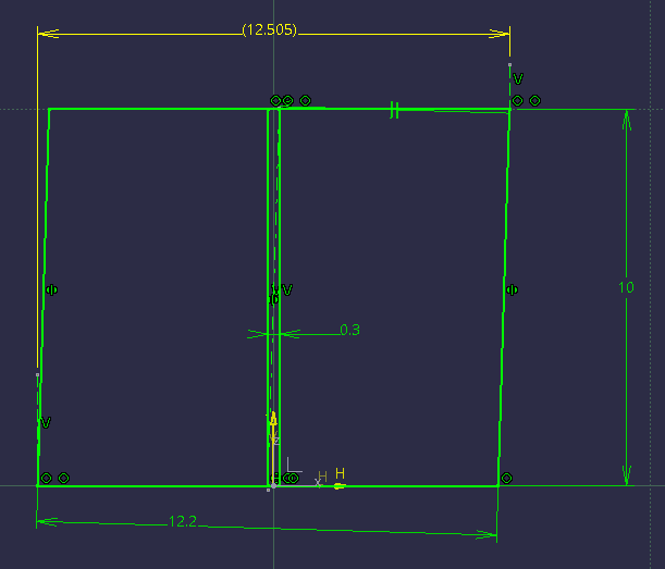
This how I calculated RAME from CAD drawing
 
The way it's measured seems correct, but the result seems odd. I will check it on my CAD tomorrow.
 
Sa-Ro,
Take a look at the image below.
The RAME size resulting from 0.3 inclination is slightly larger than 12.5. The shorter the cylinder the larger the envelope, because a shorter the 0.3 diameter tolerance zone the larger the inclination angle. For features taller than 20 mm I got 12.501 mm RAME envelope, consistently.
1591608058948_12.2_u7cwqa.png
 
Burunduk,
Since you have the sketch prepared, can you check the RAME size when its UAME is at LMC? Thanks.
 
pmarc, see below
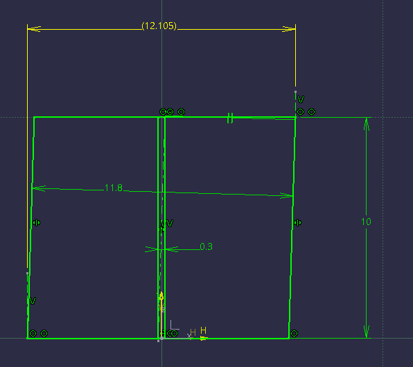
UAME=LMC=11.8
RAME size is as expected by the usual calculation. For features taller than 19 mm the RAME size is consistently 12.101.
11.8_ez4rjt.png
 
Hi Burunduk

I have calculated for 20 mm height and arrived dia 12.5 exactly (earlier 12.34 was wrongly calculated).

Even though it is 12.5, the feature will pass thru the VC of 12.5 gauge. No need to consider datum shift in that video - if location is exact.
 
 https://files.engineering.com/getfile.aspx?folder=f40ae0e9-eb13-4526-9cb2-935207ee670c&file=123.PDF
Sa-Ro,
In principle, a 12.2 size feature inclined within 0.3 and with exact location should indeed produce a 12.5 mm RAME envelope, as calculated by 12.2(UAME SIZE)+0.3(THE ACTUAL POSITION ERROR).
The few additional microns I got at measurement only show that the calculation is not 100% accurate, especially for shorter features, but that is not to say that the feature produced at that condition should have failed the inspection. In theory, it should have passed as you suggest (actually it's a borderline situation so it depends on the gage accuracy). But, in the Tec-Ease video, the feature might have been produced with position error (inclination only or inclination + location variation) larger than 0.3. I don't think Don said the error was 0.3. What he basically said is that the feature was produced at a condition that doesn't allow it to pass when the datum specification was RMB. 0.3 is just the allowed tolerance at MMC. Hope this helps you to make sense of the video.
 
While I think this is an interesting tangent, it really doesn't follow from the tec-ease example shown. The example utilizes a hard gauge which would only evaluate your part/feature to the surface interpretation. The discrepancy you are measuring in CAD is due to the difference between the resolved geometry (axis) interpretation and surface interpretation.

In principle, a 12.2 size feature inclined within 0.3 and with exact location should indeed produce a 12.5 mm RAME envelope

It won't, you just showed it won't. This isn't because "the calculation is not 100% accurate" its the difference between the surface and resolved geometry interpretations. It will however approach 12.5 as the height of the feature approaches infinity for the resolved geometry case.

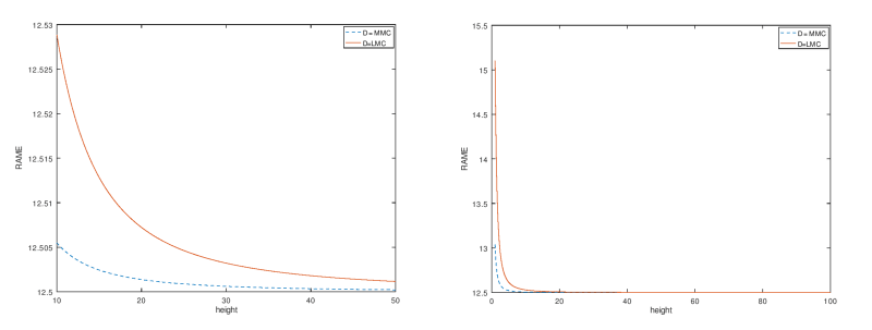
Also note your second figure you have evaluated the feature at LMC, since this feature is specified with MMC position you would have 12.2-11.8=0.4 of bonus tolerance available - your total allowable orientation error being 0.7 instead of 0.3 which results in a RAME of 12.529 for a feature of height 10 for the resolved geometry interpretation.

The curves for both the MMC and LMC cases are below.

orientation_error2_gqnlpi.png
 
Thank you Burunduk and Chez311

I learned datum shift and I will utilize in my drawing.

See you all with other doubt...
 
chez311,
You introduce some valid points, but note that the subject that required clarification here is the evaluation of the RAME size of the considered feature, to see if it would pass or fail inspection with a VC gage had the position tolerance been specified with datum feature B at RMB, assuming a specific position variation due to inclination of the feature axis.

Considering this I don't think that the explanation of how to evaluate the RAME in terms of the axis interpretation is a tangent. Rather, it is the core of the matter regardless of the fact that a hard gage is used in the Tec-Ease example.

I also think it is good to remember that the VC boundary which is used in the surface interpretation, is rooted in the axis interpretation; the calculation is the MMC size plus the value of the tolerance zone size for the axis. If it wasn't that way, MMC tolerances wouldn't be specified the way they are. If the two interpretations are fundamentally detached from each other, why not simply specify directly any diameter larger than the MMC in the feature control frame? For example: |POSITION|DIA.12.5(B)|A|B|C|, where (B) is a modifier I just made up, standing for BOUNDARY.

chez311 said:
It won't, you just showed it won't. This isn't because "the calculation is not 100% accurate" its the difference between the surface and resolved geometry interpretations.

The calculation is not 100% accurate exactly because of the difference between the surface and axis interpretations, so I'm not sure I follow the logic here. I mentioned from the beginning that the calculation is an approximation.
While the difference is there I don't think that this discrepancy is where the focus should be when answering the type of question that was asked. Perhaps it was also needed to add that it's the same formula and the same approximation that the VC boundary calculation is based on.
 
Also, note that pmarc didn't ask for the absolute maximum RAME for the "feature at LMC" case which utilizes the entire available bonus tolerance. If this is what he intended to ask I failed to conclude that intention, therefore my sketch is based on the same 0.3 axis inclination that was discussed.
pmarc said:
Burunduk,
Since you have the sketch prepared, can you check the RAME size when its UAME is at LMC? Thanks.
 
I also think it is good to remember that the VC boundary which is used in the surface interpretation, is rooted in the axis interpretation; the calculation is the MMC size plus the value of the tolerance zone size for the axis. If it wasn't that way, MMC tolerances wouldn't be specified the way they are. If the two interpretations are fundamentally detached from each other, why not simply specify directly any diameter larger than the MMC in the feature control frame?

It depends on the paradigm in which one is considering it. If you only think of 0.3 as the tolerance zone for the axis then it seems so. One could also think of it as simply a boundary of diameter 0.3 larger than the MMC size. MMC is at its core a surface control. Anyhow it matters little, at the end of the day they are two different calculations which only produce the same solution under certain special conditions. They are obviously related, but also clearly divergent, calculations.

I could only begin to guess why you might suggest anything relating to the symbol used in the FCF. Both interpretations are utilized for MMC (for which the surface interpretation takes precedence) where (M) is used to denote MMC, not the interpretation utilized.

While the difference is there I don't think that this discrepancy is where the focus should be when answering the type of question that was asked. Perhaps it was also needed to add that it's the same formula and the same approximation that the VC boundary calculation is based on.

You had already mentioned this discrepancy, even going so far as to note how this discrepancy changes with feature height. I didn't add something that wasn't already there, only to clarify and flesh out why this discrepancy occurs.

To your last sentence, if you mean the VC boundary calculation (MMC + geometric tolerance) it is not based on an approximation, it is an exact calculation which establishes the boundary in terms of the surface which may not be violated. It would be more accurate to state that evaluating this in terms of allowed variation of the axis, whether in the CAD layout you showed or utilizing the equations found in Y14.5.1, could be considered an approximation of the surface interpretation.
 
Burunduk said:
Also, note that pmarc didn't ask for the absolute maximum RAME for the "feature at LMC" case which utilizes the entire available bonus tolerance. If this is what he intended to ask I failed to conclude that intention, therefore my sketch is based on the same 0.3 axis inclination that was discussed.

I was hoping you would enlarge the tolerance zone, thus axis tilt, to account for bonus tolerance. The point of my question was to show you that the extreme value of RAME is not for MMC case but for LMC case.


Burunduk said:
If the two interpretations are fundamentally detached from each other, why not simply specify directly any diameter larger than the MMC in the feature control frame? For example: |POSITION|DIA.12.5(B)|A|B|C|, where (B) is a modifier I just made up, standing for BOUNDARY.

The technical realization would probably have to be a bit different to include cases where it is impossible to define a virtual condition boundary of a single size (e.g. for irregular features), but I agree with the idea. The plots created by chez311 clearly/objectively/mathematically show that the two interpretations should not be considered equivalent, therefore using the same GD&T notation to define two fundamentally different things is a bad idea, in my opinion.

Alternatively, to solve the problem, the standard could have clearly prohibited the resolved geometry/axis interpretation for geometric tolerances at MMC or LMC. But knowing that the resolved geometry/axis interpretation is definitely much more commonly used in industry than the surface interpretation, I am afraid that this is not going to happen any time soon, if ever.
 
Also, note that pmarc didn't ask for the absolute maximum RAME for the "feature at LMC" case which utilizes the entire available bonus tolerance. If this is what he intended to ask I failed to conclude that intention, therefore my sketch is based on the same 0.3 axis inclination that was discussed.

Changing the diameter of the considered feature without changing the amount of orientation error or the height does not change the trigonometric relationship, it only changes the size of the boundary/RAME by the same amount. Ie: when the feature is at LMC but remains at the same inclination/orientation error the RAME changes by the amount the diameter changes (12.2-11.8=0.4) clearly shown by the difference you showed (12.505-12.105=0.4). This can surely be accomplished in CAD, but comes up with the same solution as 12.505-(12.2-11.8)=12.105

I did't really mean to assume what pmarc might have actually intended though I was reading between the lines a bit, I simply thought it was pertinent (and possibly interesting) to point out that when considered at LMC with the additional bonus tolerance the discrepancy increased. From the latest response, it seems I may have read between the lines correctly.
 
chez311 said:
It depends on the paradigm in which one is considering it. If you only think of 0.3 as the tolerance zone for the axis then it seems so. One could also think of it as simply a boundary of diameter 0.3 larger than the MMC size. MMC is at its core a surface control. Anyhow it matters little, at the end of the day they are two different calculations which only produce the same solution under certain special conditions. They are obviously related, but also clearly divergent, calculations

In the 2009 standard, Virtual Condition is developed as a concept in chapter 2, where figures 2-12 and 2-15 show how it's derived from the extreme variations of the feature considering the tolerance zone for the axis and the feature's MMC size. Not differently from an outer boundary for an external feature or an internal boundary of an internal feature - RFS, as shown on related figures clearly associated with the resolved geometry interpretation. If the development of the limiting boundary for both interpretations is rooted in the resolved geometry interpretation, the two concepts surely can't be that much divergent.

Do you have a suggestion for any immediate, Y14.5-based way (and without CAD modeling) to point out that a feature produced with UAME size 12.2 and axis inclination within 0.3 can't be of RAME size of 12.34 (as was incorrectly evaluated) other than to use the same calculation that the surface interpretation utilizes to roughly evaluate the RAME resulting from the axis condition as described?

chez311 said:
I could only begin to guess why you might suggest anything relating to the symbol used in the FCF. Both interpretations are utilized for MMC (for which the surface interpretation takes precedence) where (M) is used to denote MMC, not the interpretation utilized.

To avoid making someone think that 12.5 in my example is the size of the tolerance zone for the axis. If you don't like the idea of a modifier another option could be a BOUNDARY notation under the FCF as the past practice. Of course, this is all just a "could be if not..." scenario not to be analyzed too deeply.

chez311 said:
It would be more accurate to state that evaluating this in terms of allowed variation of the axis, whether in the CAD layout you showed or utilizing the equations found in Y14.5.1, could be considered an approximation of the surface interpretation.

Again, concluding from how the VC boundary is developed in the standard, I can't say I share this point of view.
 
pmarc said:
The plots created by chez311 clearly/objectively/mathematically show that the two interpretations should not be considered equivalent, therefore using the same GD&T notation to define two fundamentally different things is a bad idea, in my opinion.

They are not equivalent, but I have my doubts regarding "fundamentally different", partly because of the chapter 2 figures but not only. To me, the identical symbology for the two cases indicates that even if they produce different results with some level of discrepancy changing from case to case, they are rooted in the same general concept. The calculation used for the VC boundary as is - is simply the quick and practical way to do the math for the boundary size based on the MMC size and tolerance value, without complex math/trigonometry or software assistance, just approximating the value of the maximum "true" RAME size. It seems to result in a somewhat more stringent requirement for the surface interpretation but simplifies the calculation.

chez311 said:
Changing the diameter of the considered feature without changing the amount of orientation error or the height does not change the trigonometric relationship, it only changes the size of the boundary/RAME by the same amount.

Not necessarily. For the same feature at 5mm height, the difference between the RAME sizes when the axis inclined within 0.3 and the UAME size changes between 11.8 to 12.2 is 0.401, not equal to the change in UAME diameter. When the axis inclination increases to be within 0.5, the RAME difference resulting from the same change increases to 0.402. For a 0.6 inclination, it's 0.403.
 
The calculation used for the VC boundary as is - is simply the quick and practical way to do the math for the boundary size based on the MMC size and tolerance value, without complex math/trigonometry or software assistance, just approximating the value of the maximum "true" RAME size.

The calculation does not approximate the value - it is exactly the value of the maximum RAME size (for an external feature, or minimum for an internal feature) for the surface interpretation, and since the surface interpretation takes precedence for MMC per Y14.5 then this is the precise limit that the feature must not violate.

Note that these trigonometry calculations are relatively simple and clear cut for orientation error only - when form error (or a combination or orientation and form error) are considered the answer becomes even more complex, and the true RAME size becomes even less connected to any evaluation in terms of the axis. The RAME is actually itself derived from the surface, this becomes obvious when any form error is introduced - the RAME isn't even involved in the equations for axis interpretation, it just happens to be easy to calculate from axis deviations when there is no form error.

Its worth noting that the measurements you made in CAD for the RAME are the same as would be made under the surface interpretation and actually show the disconnect between the two interpretations. For example in your (8 Jun 20 09:28) post the feature passes per the axis interpretation (axis falls within 0.3 tolerance zone) but fails the surface interpretation (RAME of 12.505 greater than VC of 12.5). Therefore the feature is nonconforming.

It seems to result in a somewhat more stringent requirement for the surface interpretation but simplifies the calculation.

The surface interpretation is the final word for MMC - which essentially states that the surface may not violate a boundary of size MMC+geometric tolerance for an external feature and MMC-geometric tolerance for an internal feature. When instead evaluated in terms of the axis, this is either more or less stringent depending on the situation - it will either reject good parts (ie: due to form error, see Y14.5.1-1994 fig 5-1/Y14.5-2009 fig 7-6) or accept bad parts (ie: due to orientation error, see Y14.5.1-1994 fig 5-2).

Not necessarily. For the same feature at 5mm height, the difference between the RAME sizes when the axis inclined within 0.3 and the UAME size changes between 11.8 to 12.2 is 0.401

I stand corrected, I did not go out to enough decimal places to notice the difference. It has a much smaller effect on the size of the RAME, and it was clearly not the conclusion the question was meant to elicit (actually you didn't even go out to enough decimal places in your initial response to make this conclusion either) but you are correct, it does make an impact.
 
chez311,
I think you're missing the point here. It is not really about what interpretation takes precedence for conformance.
My speaking of one type of evaluation being an approximation of the other is in the context of what was explained to Sa-Ro, and that is how to evaluate the RAME size of a feature assuming that it is out of true position within a specific amount of tolerance (0.3) due to an error in axis orientation. See his sketch from 7 Jun 20 03:41.

Sorry for repeating my question again, but if you think that since Sa-Ro introduced the problem dealing with an axis, there is a way to quickly evaluate based on Y14.5 that the RAME of the feature should be near 12.5 (without CAD models or overkill trigonometry) which is better / more correct than using the same formula that the calculation of the limiting boundary for the surface interpretation is based on, please share. Otherwise if like me, the first thing you would do is to add the value of the utilized position tolerance shown in his sketch to the MMC limit (12.2+0.3), then you should know that the link between the two interpretations is unbreakable, and honestly I have no idea what point you are trying to make here. Sure axis and surface produce different results to some level of discrepancy, and it's true that one takes precedence over the other for conformance, but is any value added by all that here considering the problem?

Note taken that form error is an additional factor and that there is no way to tell which requirement is more stringent as it would depend on the exact situation, but that only confirms that there is no way to tell for sure if a realistic feature which is similar to the one in Sa-Ro's question but not identical to my simplistic sketch would pass or fail the inspection with the hard gage shown in the video. As I mentioned to Sa-Ro, it's a borderline situation and there is no reason to assume a realistic feature would not conform. Since the borderline pass/fail condition is the same for both the axis and surface interpretations, this further emphasizes their connection. In the end, there is a good reason why para. 7.3.3.1 in the 2009 standard calls them "Surface Interpretation" and "Axis or Center Plane Interpretation" - that is to say, the interpretation changes but the concept remains the same.

chez311 said:
It has a much smaller effect on the size of the RAME, and it was clearly not the conclusion the question was meant to elicit (actually you didn't even go out to enough decimal places in your initial response to make this conclusion either)

As admitted already, I suppose I didn't do a good job at guessing pmarc's intent. However as you've seen there are also other nuances to the subject beside of the maximum possible RAME size, and since "maximum" or "extreme" wasn't mentioned it was also reasonable to think that the intent was to examine the relationship between UAME size difference and the resulting RAME size difference for the specific orientation error that was discussed. And by the way, both the sketches I made show 3 decimal places for the RAME size.

 
honestly I have no idea what point you are trying to make here

Nor do I know what point you are trying to make.

I saw a gap in some information and attempted to fill it, which coincidentally allowed me to do some calculations I had been meaning to do but never got around to. Perhaps I should not have labeled it as tangential, you were simply trying to show why OP's calculation was incorrect.
 
Status
Not open for further replies.

Part and Inventory Search

Sponsor