Continue to Site

Eng-Tips is the largest engineering community on the Internet

Intelligent Work Forums for Engineering Professionals

  • Congratulations KootK on being selected by the Eng-Tips community for having the most helpful posts in the forums last week. Way to Go!

Datum Strategy with Small Surfaces

Status
Not open for further replies.

Tomasz_P

Automotive
Jul 5, 2024
2
Hi, Apologies this is a very basic question.
I have a small machined part. Is it ok to choose relatively small (and separated) surfaces as the primary and secondary datum. I could choose the base of the part as the primary datum but I am reluctant because it is unimportant for the function. It would possibly easier for inspection though? The primary datum will be brazed to a mating part and the secondary surface will mate to seals.
I have attached a cropped image. The rest of the part is about the same size again but narrower.
Alternative suggestions welcome!
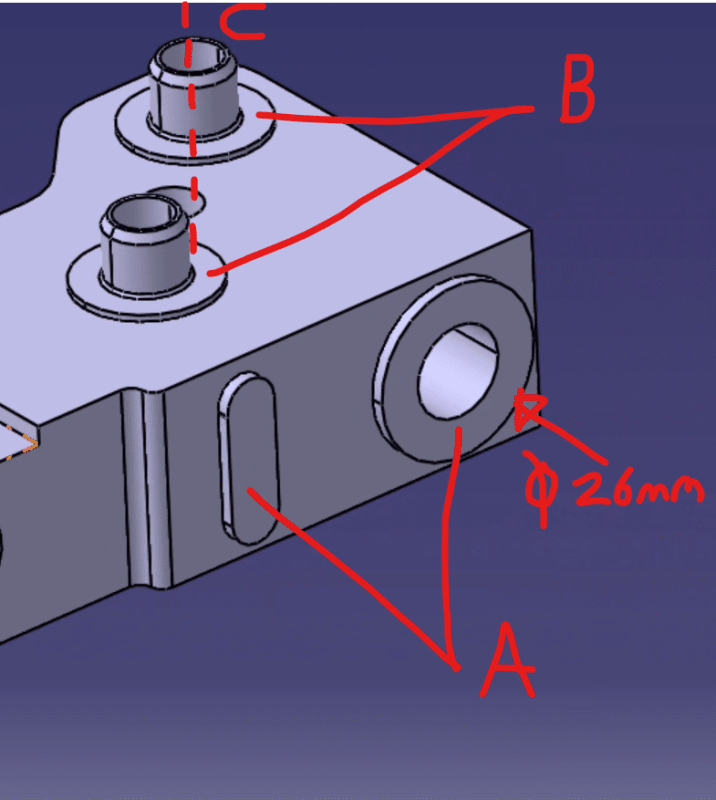
Screenshot_2024-07-05_180143_cng0ds.png
 
Replies continue below

Recommended for you

About the selection of datum features, ASME Y14.5 states in para. 7.8:

"To ensure proper assembly, corresponding interfacing features of mating parts should be selected as datum features. However, a datum feature should be accessible on the part and of sufficient size to permit its use."

No definitive method is suggested to quantify what may be a "sufficient size", so it's subjective to whoever makes the decision.

My opinion is that generally, when the interfacing features are considered reliable/large enough for mounting the part in the functional application, they are also good enough for use in creating a datum reference frame for controlling the location and orientation of other features on the part. Also, "qualifying" the datum features by applying proper geometric tolerances to them, generally minimizes the issues of un-reliability associated with small areas or sizes. However, I'm not saying that there may not be any exceptions to that.

The risk with selecting non-functional features as datum features is the increase of tolerance stack up from the part's interface to the features that need their location and orientation under control, to fit with mating parts or serve their purpose generally. To compensate for the stack-up increase, tighter tolerances are often required to relate the selected datum features to the functional interface. So the convenience of inspection comes with the cost of tighter requirements.

Alternatively, design changes may be considered when possible, to make the interfacing features larger.
 
Thank you for your advice [bigsmile]. I kept with them in the end but changed the order.
 
This part sort of looks like a machined cylinder head with valve guides. On a part like this, since it's machined on all sides I would use the bottom surface as Datum A, the two surfaces you currently show as Datum A as Datum B, and the right surface as Datum C. Then use positional tolerancing for the valve guide holes.
 
Status
Not open for further replies.

Part and Inventory Search

Sponsor