Eng-Tips is the largest engineering community on the Internet

Intelligent Work Forums for Engineering Professionals

  • Congratulations waross on being selected by the Tek-Tips community for having the most helpful posts in the forums last week. Way to Go!

Datum target relationship to features 1

Status
Not open for further replies.

Jay8833

Automotive
Apr 19, 2023
7
0
0
US
Loving this forum and the great info you all share!
I have a question regarding Datum Targets.
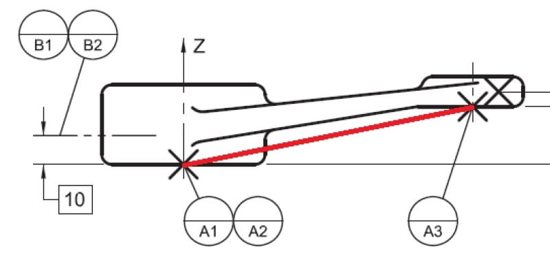
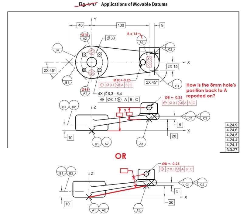
In the 2009 standard, Fig 4-47 shows datum target points A1-A3 on different planes. How exactly are the four holes related to the Datum A target points? They wouldn't be perpendicular if A1-A3 are creating a plane. I feel like I'm missing something here and would appreciate some guidance.
Thanks!
 
 https://files.engineering.com/getfile.aspx?folder=cebd12d0-3fe8-4a88-be20-5cfd93a96f93&file=ASME_Y14.5_2009_FIG_4-47.jpg
Replies continue below

Recommended for you

Hi, Jay8833:

A1, A2 and A3 are not datums. They are datum features rather. These datum features establish a datum plane at bottom of the part. Does this make any sense to you?

Best regards,

Alex
 
4-47_PLANE_ffqqkx.jpg
 
Does that change if we use target areas instead? Are the target areas still treated as points even if they are planer themselves?
Is this outlined somewhere in the 2009 standard?
ASME_Y14.5_2009_FIG_4-47_MODIFIED_fzwlny.jpg
 
Jay8833 said:
So the 3 Datum feature target points establish a datum plane at the resultant angle?
(pic attached)

The 3 datum target points establish a plane that passes through A1 and A2 and offset by 20 mm per the basic dimension from A3. This plane is the XY plane of the coordinate system representing the datum reference frame in the drawing.
 
Targets describe the nominal fixture upon which the part will be placed for inspection. The coordinate system is of the inspection fixture, not the part. The part is placed and then inspected in that coordinate system.
 
3DDave said:
The coordinate system is of the inspection fixture, not the part. The part is placed and then inspected in that coordinate system.

No one said that the coordinate system is of the part. It is an integral part of the datum reference frame, and it's established from the datum feature simulators, not from the actual part.
 
The datum is not a plane that intersects those three targets in a diagonal fashion -- that would be true only if the 20 mm basic dim were not given. Instead, the datum plane is horizontal (in the viewer's perspective). On a physical fixture, the spherical ball supporting A3 should be 20 mm taller than the other two spherical balls (I'm assuming that we're dealing with the figure from the standard, where the targets are points).

In theory, the datum plane could be at any height; you could add extra basic dims in the z direction to place the theoretical datum anywhere in space. So for the most recent picture above, the first option is more correct, and either of the blank basic dim boxes would be acceptable.

John-Paul Belanger
Certified Sr. GD&T Professional
Geometric Learning Systems
 
Thank you John! When it comes to reporting the deviation of the Ø8mm hole back to A... Is it correct that the hole's axis needs to fall in tolerance back to all 3 datum feature simulators (target areas in this case)? (or if I only put dimension X on the drawing, only the value back to datum A3 would be reported?)
Also, is this type of thing called out in an ASME measurement standard?

Thanks a lot for your help!
target_dims1_rmxuym.jpg
 
You fix the true position from the datum features you used as datum references. Since you used [A|B|C] you set up the datum reference frame for that feature. You aren't measuring back to any of them - you are measuring to the true position that is located relative to the datum features you referenced.
 
You'd measure the position deviation from the true (perfect) position, and that would all be relative to the theoretical datum A (not datum feature A and not target A3) and B and C.
So for the latest graphic, if X is shown it's probably best to report that deviation (also considering B and C). However, you could just as well report the deviation from X+20, since plane A is broken/offset.

John-Paul Belanger
Certified Sr. GD&T Professional
Geometric Learning Systems
 
Unfortunately chosen "X" dimension is in the Z direction.

The true position deviation has both delta-X and delta-Z components as measured from the true position for the feature.

That coordinate system is shown; 20+X is the nominal value and should be subtracted from any measured Z coordinate to produce the delta-Z contribution.
 
Status
Not open for further replies.
Back
Top