Eng-Tips is the largest engineering community on the Internet

Intelligent Work Forums for Engineering Professionals

Datum targets and their form and orientation errors controlled 6

Status
Not open for further replies.

greenimi

Mechanical
Nov 30, 2011
2,251
0
36
US
ASME Y14.5-2009

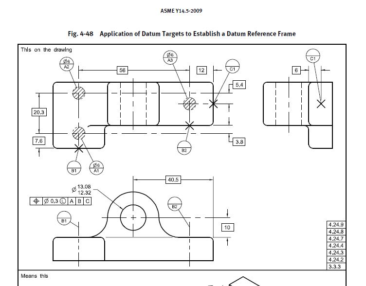
Question #1: I have an internal checker who is claiming that would be wrong (illegal) to add flatness on the surface where datum targets area A (Ø6) are shown.

By the same token,

Question #2: adding a perpendicularity callout (to A primary) for the surface where datum targets lines B are shown (considering that feature is continuous/planar and not, as shown, stepped, separated by basic dimension). The same checker is claiming that such approach is against the Y14.5 standard.

He does not want adding the perpendicularity (or flatness for that matter) because there are no figures in the Y14.5 where such method is shown.
Is this argument good enough to consider it valid? Is this practice against the standard?


Qff_-_Copy_scjtef.jpg
 
Replies continue below

Recommended for you

The ASME standard certainly shows examples where datum features are "qualified," that is, toleranced for their own accuracy to each other. Check out Fig. 7-2, where D is tagged with flatness and E is then perpendicular to D.

So is this person's issue that the datums in question are formed by targets? So what?

A case could be made that the surface where the A targets are doesn't functionally need flatness (because the mating part may only touch those three spots). If that's true, then we might still do profile of a surface to get the three targets somewhat coplanar with each other.

John-Paul Belanger
Certified Sr. GD&T Professional
Geometric Learning Systems
 
Belanger said:
Check out Fig. 7-2, where D is tagged with flatness and E is then perpendicular to D.

Is your fig 7-2 a typo? I cannot find what you are talking about covered in 2009 standard....
If you are referencing the 2018 then that figure does not have datum targets (which is my main inquiry)
 
I was looking at 2018. In 2009 it would be Fig. 4-2.
But my point is that if your colleague is fine with the figure I gave, why would having targets change things?

John-Paul Belanger
Certified Sr. GD&T Professional
Geometric Learning Systems
 
Belanger said:
But my point is that if your colleague is fine with the figure I gave, why would having targets change things?

Because he treats datum targets a little different than datum features based on the reasoning that no flatness/ orientation controls are shown on the datum target paragraphs on the Y14.5 standard (2009).
So you are saying that (adding flatness and perpendicularity) is definitively not illegal in those cases? Am I correct in my interpretations of your replies?

What arguments do you have to support this assessment? I would like to show him paragraphs from the standard if all possible to put this issue to rest once for all.

I cannot find anything related to this matter. Could you help, please?

 
I might say the burden is on him to prove things (why does lack of a picture equate with the standard forbidding something?).
But here are two more thoughts:

--Since the datum plane is created just from areas A1, A2, A3, a flatness tolerance on the overall surface is not doing much to the datum itself (except ensuring coplanarity of the three targets). Most of the real estate is outside the target areas, so it's doing flatness just like any other non-datum surface.

--Also, have him check out 2009's Fig. 4-42 (the vehicle hood). Is there a geometric tolerance affecting the datum target areas?

John-Paul Belanger
Certified Sr. GD&T Professional
Geometric Learning Systems
 
Why is there any argument? Is there an example in the standard of this applying to an engine block, a turbojet engine, an electric motor? If not, are these things that Feature Control Frames per Y14.5 cannot be applied to?

The requirement applies to the surface, not the datum targets.
 
Belanger said:
--Also, have him check out 2009's Fig. 4-42 (the vehicle hood). Is there a geometric tolerance affecting the datum target areas?

J-P,
No, it is not. That's exaclty his point.Would be "illegal" to have perpendcularity of the right surface (where B is shown) to A primary?
Would be "illegal" to add a datumless profile (to control the form only) for the surface where A are shown?

Hence I am confused. Are you supporting his assessment?
Could you, please, clarify your point?


3DDave said:
The requirement applies to the surface, not the datum targets.

I understand that.
But his point is that would be "illegal" to add a form control on the features where the datum targets are applied.
Also his point is that would be "illegal" to add an orientation control for the surfaces/ features where datum targets (B in this case) are applied relative to a datum which is defined by datum targets (datum targets A)
 
Since there isn't much in any version of the Y14.5 standard that says what one is not allowed to do (I think there are just a few) and certainly doesn't say anything about this, whatever reasoning is being brought to bear with the word "illegal" is made up of delusional thinking.
 
3DDave said:
....and certainly doesn't say anything about this, whatever reasoning is being brought to bear with the word "illegal" is made up of delusional thinking.

I understand. That's why I posted. To put the "delusional thinking" to rest.
But looks like I don't have irrefutable arguments and the standard itself is very ambiguous. If my assessment above is wrong then I would like to know why.....

 
For your two questions for me... I would say it's not illegal.
For Figure 4-42, it seems that B1 and B2 are on a very small surface that is toleranced by profile. Is that illegal? Or is it OK because it includes datum B in the callout?


John-Paul Belanger
Certified Sr. GD&T Professional
Geometric Learning Systems
 
Let's go with his idea and take it to its extreme -- if the surface where A1, A2, and A3 are is not toleranced for flatness (because somehow it's "forbidden"), then what controls it from being crazy bumpy? Rule #1?

Your colleague is simply making stuff up. If a regular-style datum surface can be toleranced for flatness, there's no basis for saying that a surface with datum targets can't also be toleranced for flatness.

John-Paul Belanger
Certified Sr. GD&T Professional
Geometric Learning Systems
 
Belanger said:
Is that illegal? Or is it OK because it includes datum B in the callout?
No, it is not illegal.

Side note: 2018 standard shows even an example (fig 11-21) of such approach.
But, I don't want to stir the conversation on fig 11-21 concept.


I want to stay on datum targets (points, lines or areas) and their relationship between themsleves and the lack of standard clarity (feature form error control missing on the primary feature where datum targets are applied to; orientation error control missing for the secondary feature where datum targets are applied to/ used to used)


"the standard itself is very ambiguous"

Not in this case. As far as I know the word "illegal" does not appear in the standard, so no callout can be illegal. Even "cannot" appears only a few times.

I'd really like to see what reason they have to believe so.
 
Belanger said:
..... if the surface where A1, A2, and A3 are is not toleranced for flatness (because somehow it's "forbidden"), then what controls it from being crazy bumpy? Rule #1?

Nothing. No control. Left to the mercy of the "nature" :)[bigsmile].
The argument is: because that is why they are using the datum targets, because there is "TOO MUCH" variation on the feature, whatever too much means, and they are not using datum feature.
If you wanted to control the feature itlsef (form error, orientation) you would use datum feature and not datum targets.

That's his argument


The standard concentrates on showing how controls work, individually, not on what combinations are suitable or useful.

the lack of standard clarity (feature form error control missing on the primary feature where datum targets are applied to; orientation error control missing for the secondary feature where datum targets are applied to/ used to used)

isn't part of the standard to clarify. It's unfortunately not a tutorial in good practices.
 
Greenimi -- even though the standard's graphic doesn't have size dimensions, Rule #1 would indeed control the flatness of that surface (assuming it's a rigid part).


John-Paul Belanger
Certified Sr. GD&T Professional
Geometric Learning Systems
 
Belanger said:
... even though the standard's graphic doesn't have size dimensions, Rule #1 would indeed control the flatness of that surface (assuming it's a rigid part).

I agree with you J-P.
But see his argument is why the standard does not provide clarity in this area?
If we use 4-53/ 2009 for arguments (and I HATE to bring new figure into the conversation), datum feature B is shown with datum feature SYMBOL (succsion cap symbol) and has also datum target points (B1, B2 and B3) I would agree with you that Rule#1 is applicable to the outside diameter (Ø170±0.1).
But, for some unknown reason, does NOT have any relationship between primary and this OD feature "B" (no perpendicularity callout shown for datum feature B). His reason IS: BECAUSE datum targets are used (that's why no perpendicularity!! is this a "good enough" reson: I don't know: I am asking)

The same arguments he is using for the flange feature: no flatness control, BECAUSE datum targets A1, A2 and A3 are used.

Why the standard (intentionally or not) avoided to use those callouts? I mean why no perpendicularity between Ø170 feature and the flange (primary)?
Why no flatness for A?


Status
Not open for further replies.
Back
Top