Continue to Site

Eng-Tips is the largest engineering community on the Internet

Intelligent Work Forums for Engineering Professionals

  • Congratulations KootK on being selected by the Eng-Tips community for having the most helpful posts in the forums last week. Way to Go!

Datum Translation application

Status
Not open for further replies.

AMontembeault

Mechanical
May 13, 2014
26
Can a datum translation modifier be used when the datum is a planar surface? I can't see anything in the standard which seems to explicitly prohibit this, but every example out there I can find typically only demonstrates this concept using a datum derived from a feature of size (typically a hole or pin).

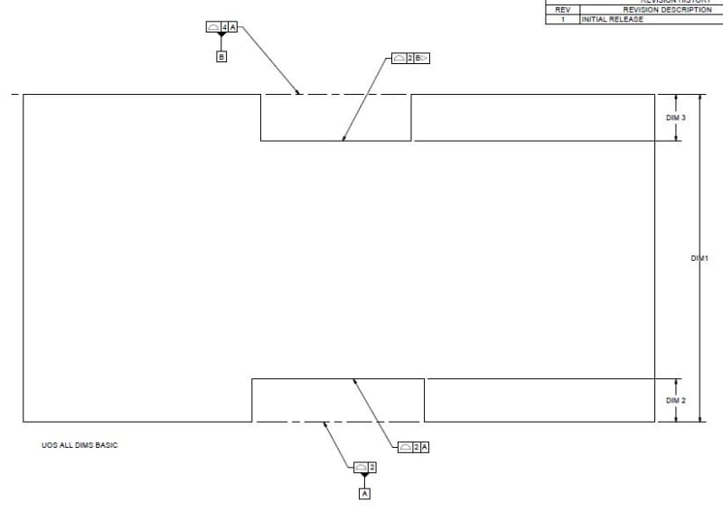
My application is, I have a rectangular part, with notches cut on opposite ends (Call them datum A and Datum B). I want to control the depth of the notches relative to their respective end face. So my thought was, control the notches on the A datum face back to A, control B datum face back to A, and control the notches on B back to B with a translation callout (otherwise B is controlled at a basic dim back to A, which would give me the wrong stack-up of tolerances).
 
Replies continue below

Recommended for you

Sure it can, though it only has an impact if said planar datum feature has location constrain to a higher order datum feature.

A sketch would help but your example does not sound like a proper use of the datum translation modifier. I don't even think it would do what you expect it to do. I don't think you need the modifier to be able to control a notch on A to A, and a notch on B to B, and B relative to A. Depending on your application, calling out B and A as separate datum features, while perhaps convenient, might not reflect function. Seems like you could get the result you desire with composite/multiple single segment profile tolerances.

Again more information about the application and a sketch would help.
 
Here is a simplified sketch:

Capture_bbsaun.jpg


In this design, DIM 2 and DIM 3 are somewhat critical for fit-up. The part is also too massive to be accurately measured with an arm based CMM. In older days, I would have just used limit dimensioning on DIM 2 AND 3, but I'm trying to be consistent with ASME Y14.5 best practices. If I controlled the profile of the top notch to A, then I'm worried that the stackup between datum surface B and the top notch profile would be too large. Because B is held at a basic dimension to A, I thought maybe I would need a translation modifier.
 
In that sketch, wherever datum B goes (based on its profile control), the other tolerance that references B will try to follow it. So there's no need for a translation modifier.

John-Paul Belanger
Certified Sr. GD&T Professional
Geometric Learning Systems
 
AMontembeault said:
If I controlled the profile of the top notch to A, then I'm worried that the stackup between datum surface B and the top notch profile would be too large.
If this is your concern, you probably shouldn't have a tolerance zone for the notch controlled to B which can float in location without constraint. As you have it shown the top notch only has to be oriented to B not located (datum feature simulator for B is free to translate).

Ironically, removing the datum translation symbol would get you exactly what you want - a surface controlled in orientation and location to B instead of A. You could add a parallelism refinement if desired.

FYI you probably want to use the "2X" notation even when using an extension line to connect the two surfaces like Y14.5-2009 fig 4-23.
 
Status
Not open for further replies.

Part and Inventory Search

Sponsor