Eng-Tips is the largest engineering community on the Internet

Intelligent Work Forums for Engineering Professionals

De-Aliasing the Input to a Datalogger 6

Status
Not open for further replies.

Sparweb

Aerospace
May 21, 2003
5,103
0
36
CA
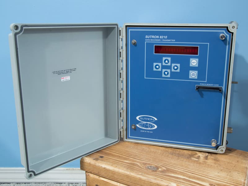
Most of what I have learned about anti-aliasing in ADC inputs involves filters built into the ADC, or oversampling, and other such strategies that focus on changes to the system logging the data. I'm stuck with a datalogger which I'm not not able to modify for this supposedly simple project, but I've got too much aliasing going on. The external circuit that transforms the input signal to the scaled signal that the datalogger can read is the place to fix this, and seems to be the source of the problem. For those interested, here is the datalogger:

Sutron8210_sn961400_FrontPanel_waccvx.jpg

Specifications

A neighbour of mine has made spot-measurements of his house voltage and is concerned about the safety of appliances in his house. He tells me he has seen readings higher than 130V, which is outside the allowable variation by local utility regulation. We want to record some evidence of our own, to understand the problem better, before pursuing the matter with the utility company or paying a consultant that the utility will respect. My goal is to provide the datalogger with a DC output about 4.0 volts which is scaled to the input voltage, taken from the 120VAC main power line. If the line drifts up to 130VAC, then the DC signal should rise from 4.0 to 4.3. The datalogger can re-scale the data, but it doesn't seem to deal with ripple very well.

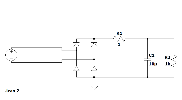
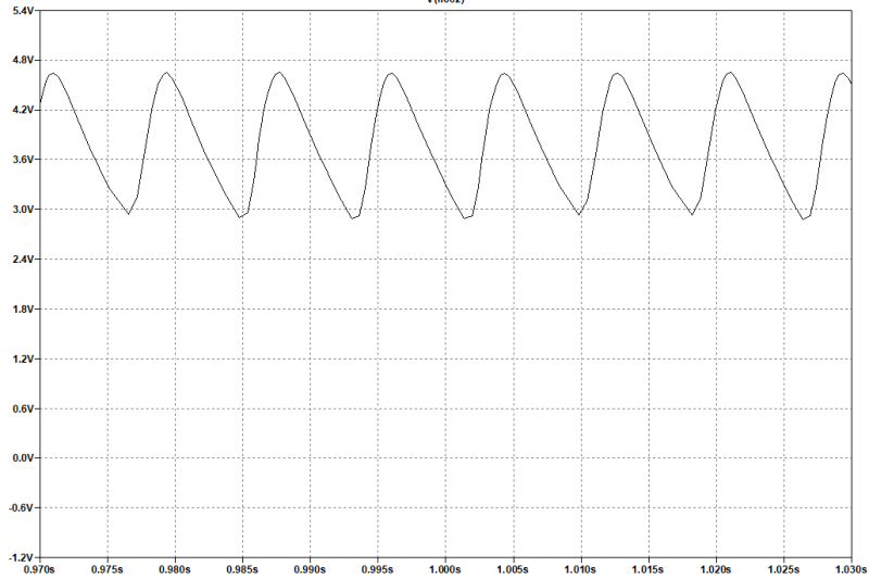
To make the scaled DC signal, I made a simple linear DC power supply circuit with no regulation. The AC is stepped down to about 4VAC through a transformer. The output AC is turned into DC with a full-wave bridge rectifier. Across the rectifier I have connected a 10uF capacitor and a 1k resistor. I believe this provides a DC output that will "follow" fluctuations in line-in AC voltage in a linear proportion.

Unregulated-Linear-Power-Supply_vvexu4.gif


I believe that aliasing is the problem because my digital multimeter gives readings that wander up and down, and I've hooked the circuit up to the datalogger and get the same result. Meanwhile the needle on my analog meter stays steady as a rock if I measure the same thing. The true RMS DMM readings wander up and down by 10%, so I do believe the sampling is the problem. Both the datalogger and the digital multimeter behave the same way. Simultaneous measurements of AC or DC voltage with my analog meter shows all steady. I can't change the sampling rate of the DMM or the datalogger.

I have already increased the capacitor from 1uF to 10uF with no measurable effect. Should I try more?

Is there a way to filter or smooth out enough of the ripple that I can limit the aliasing to 1% (0.05VDC)?

Is there a different circuit that will do what I want better than the linear power supply?


No one believes the theory except the one who developed it. Everyone believes the experiment except the one who ran it.
STF
 
Replies continue below

Recommended for you

The analog meter probably has a lower input impedance, which would tend to "settle down" the power supply you've built.

An inexpensive analog meter might have an input impedance of 1k ohm per volt (of range). A DVOM might easily be 10M ohm.

The power supply as shown, with a light load like a DVOM, will tend to float to the most recent peak voltage, including (to some degree) the otherwise insignificant little bumps.

edit: You've got a 1k ohm resistor. Which should be sufficient. Sorry I failed to notice it at first.
 
Aliasing are the measuring artifacts caused when the input signal includes significant frequency spectrum components that are above sampling rate, with a 2:1 ratio as at least two samples are needed to define a cycle.

Most modern DVOMs these days are "True RMS", so they'll be sampling well above the power line frequency of 50 or 60 Hz. Many will be reasonably accurate even to around 1 kHz. There are now such DVOMs for $20 price class, nearly ideal except for some legitimate safety concerns if used on high energy circuits.

So, as long as the power line doesn't carry significant levels of strange interference, then hopefully aliasing isn't actually an issue. Also, your power supply is emitting a DC voltage, plus or minus any noise that gets through.

Edit: specification mentions up to 32 kHz input but on the Counter inputs. Doesn't give any details about ripple rejection on the analog voltage inputs.

Maybe add more filtering to your power supply, like a series resistor and another capacitor (obviously can't use a regulator). Choose your preferred time constant, but it'll need to be at least a good fraction of a second.
 
Some DVOMs will provide MIN and MAX registers. So in principle, set it to AC (high voltage), the probes could be jammed in the outlet, reset the MIN/MAX registers, and let it run.

There'd be some safety considerations...

It probably wouldn't time stamp.

--

Going back to your original concept, you might need to put a modest load resistor on your power supply. That'll tend to bring it from something like a representation of peak voltage, towards the general direction of average (rectified average, not the zero average of AC). edit: 1k is probably reasonable.

About 40 years ago, I designed and built a little box with an expanded (offset) scale line voltage meter. Very similar concept, but with a regulated voltage to provide the baseline, so the scale on the meter was something like 100 to 140 VAC.

It probably had a lamp to put a modest load on the unregulated part of the power supply.

It worked well, as I recall.

--

Commercial power quality monitors would measure all sorts of parameters, and record and report just the exceptions.

--

(Multiple posts because I'm using a phone.)


Hi VE1BLL,
Thanks, but you will have to bear with me. I do not speak EE Jargon as clearly as I would like, and clearly this is the case.
Edit: Something else to clarify "I can't change the datalogger's sampling rate" which means the fastest sample rate for this logger is 1 second. It's a really old datalogger. There is no such thing as 1kHz sample rate for this device. So no point in exploring the ripple in detail.

I only need to feed the datalogger a signal it can use. Since the datalogger samples data like the DVM does, I compared its measurement to the DVM readings and the analog meter for a third reference. My concern is that the circuit is generating too much ripple, causing the datalogger reading to jump around. So what will clean up the ripple so that the datalogger can use the DC?


No one believes the theory except the one who developed it. Everyone believes the experiment except the one who ran it.
STF
 
"...fastest sample rate for this logger is 1 second..."

Might as well try a series resistor and then a parallel capacitor at the data logger input, with a large time constant. Enough to knock down the 60 Hz (actually 120 Hz due to the bridge rectifier) ripple.

The series resistor will act as a voltage divider with the input impedance of the data logger input, so it needs to be low resistance (less than 1k ohms). For example 220 ohms, a common standard value.

Parallel capacitor might be around hundreds of uF, garden variety electrolytic territory. For example 500 uF.

EDIT: It must be late. :)

The ripple will be dropped across the series resistor. The voltage on the data logger input will be much closer to ripple free. And still representative of the line voltage.

None of these values are critical. Consider these or anything similar as starting values. Feel free to experiment, or use what is available.

It's so much easier to eliminate ripple with a voltage regulator, but not a solution here obviously.

I'm not even considering a series inductor, as they're less practical for several reasons.
 
If you're trying to go against a PoCo you will get nowhere with your setup. Trying to measure around a rectifier is fraught with ifs/buts/gotchas and the PoCo will know that and probably blow you off.

I'd ask them to log your voltage for a couple of days which a lot of PoCos will do or get out your wallet and pick up a reasonable data logging meter.

Home Depot sells this one as an example. You can set it to log RMS voltage once every second up to once a day for 100,000 samples. If you logged the voltage (to 0.1V) every 10 seconds x 100k = 11.5days of 10 second logs and plopped that on their counter you'd get some results.

Keith Cress
kcress -
 
Right, Keith!

I ran a few LT Spice simulations and they show lots of problems with SW setup. Not to talk about those wave-forms shown. If the sine looks like a string of half arcs - there is a serious problem. That problem is more in the brain of the person that drew the wave-forms than IRL.

Original circuit:
image_t3qmkn.png


And wave-form out:
image_d7evmo.png


There are soo many problems with that wave-form. Diode voltage drop, "impulse catcher" (diodes and naked capacitor does that, very high ripple because the time constant isn't enough. And then some - like temperature dependency and other things.

Increasing the capacitor alone doesn't help much. But if the source impedance into the filter is made fairly constant by adding a 1 k load across the bridge output, increasing the resistors to 10 and 10 k and going to 100 uF capacitor, you get a smooth output that doesn't show aliases:

image_y548tc.png


Using 10+10 k will give you an effective R[sub]out[/sub] equal to 2.5 kohms and that only introduces an error around .25% - which drowns in all the other errors. It can, if needed, be easily be calibrated out of the recording.

I wonder: What problems does your neighbor have?


Gunnar Englund
--------------------------------------
Half full - Half empty? I don't mind. It's what in it that counts.
 
Thank you everyone!
I may have confused myself during the "fussing around" the other day. This morning I hooked up a different capacitor across the bridge output and this time the DC stabilized nicely. The first capacitor I soldered into the circuit probably was broken. I have a junk box of old parts that I use for tinkering. I must have drawn a dud out of it the first time. I tried a few others today, from 100uF to 1000uF and they all filtered the ripple.


No one believes the theory except the one who developed it. Everyone believes the experiment except the one who ran it.
STF
 
About for the neighbour's problem:
He has solar panels on his house & garage roof, and some of the Enphase string inverters have tripped due to overvoltage. He believes that the power provider is allowing the voltage of the lines to rise beyond limits. I can see his point, but his system is complex, and I've thought of a few other things that could be going on. I would like to test the line voltage in various places in his system. One test close to his service entrance, and one test on the solar panel's feed-in circuits where they come into the combiner panel. Spot checks aren't really the thing. We need to watch it long-term, like at least a week, to see trends if there are any.

I might make another one for myself. I'm not grid-tied, but I do get brown outs. Seeing trends in my own supply might be interesting.

FWIW: the term "neighbour" is loosely defined in big-sky country. He is several miles away from me, on a different branch of the electric transmission trunk line, but it is all owned by the same power company. Each of us is on a long thin string coming from the branch line, meaning there are many local things that could affect him that wouldn't affect me, and vice-versa.

No one believes the theory except the one who developed it. Everyone believes the experiment except the one who ran it.
STF
 
Re. The bad capacitor.

It's worth mentioning my general observation that the success rate of troubleshooting over the internet is about (first approximation) 50%.

This is due to the limitations of the medium, as compared to being there.

I'm glad it worked out.

Your neighbourhood sounds....spacious.
 
Solar on the ends of long lines is notorious for over voltage-ing the lines. It's the driving problem in causing the shift to control of power-walls and solar installations to the PoCos.

I'll bet that ultimately the solution will be a power-wall for your neighbor where the maximum from his solar will have to be fed to local storage for local reuse at night or for a more spread-out return to the gird than peak solar return with all the other remote solar all over supplying the grid right when everyone else doesn't need power.

See Rule 21

I saw somewhere, I can't find again, that showed an example of remote houses out on the grid causing excessive voltage rise that the PoCo had no real control over. This was a major reason requiring Rule 21 creation. It allows the PoCo to reduce solar injection into the grid.

Keith Cress
kcress -
 
Hi SparWeb.
1. Are the measurements being taken when the solar is on-line?

2. Have you tried contacting the customer service department of the POCO for advice and possible help?
We may or may not be on the same POCO. I had some conversations with my POCO customer service department a few years ago and found them to be very approachable.
If your friend has a digital KWHr meter it may already be measuring the voltage swings. Many of them have the capability to measure and record (per phase on a three phase system) Volts, Amps, Demand, and PF.
In another place and time, I was able to get a file of all measured parameters taken at 15 minute intervals for the preceding month.
The cost:- A two liter bottle of Pepsi, supply my own floppy disk. (I had friends).
In some cases a tech could make one trip and download the info.
In other cases it was one trip to set up the meter program and a second trip a month later to download the info.
It's worth a phone call to the customer service dept.

3. Is it possible that the solar installation is causing the problem?

4. Are there any consumers on the line, either upstream or downstream, who may be causing the problems?
A large motor starting or running may be causing issues.
There are a lot of ways a motor can cause a voltage rise.
A heavy load on your phase may cause a voltage drop which, when the motor stops will become a voltage rise, until the voltage regulator for that phase corrects.
A heavy load on another phase may cause a voltage rise on your phase.
A large motor, some distance downstream from a voltage regulator can interact with the corrected voltages and produce unexpected results.

5. Have you moved in the last few miles?
Your early posts led me to suspect that you were south of a major city.
More recent posts lead me to suspect that you are east of the same city.
If so, is there any chance of a tour of your setup some day?

6. BTW If you are rectifying your voltage you may be measuring the average voltage rather than the RMS.
The old analog meters were measured average voltage, but a form factor of about 1.1 was applied and the scales were marked to indicate the equivalent RMS of a sine wave.
The average of a distorted sine wave tended to be lower than the RMS.

7. A series reactor was mentioned. The windings of the small transformer may make an effective series reactance.

8. Consider addressing harmonics closer to the source; Put a large capacitor on the transformer input to kill the harmonics.
Scotty, Gunnar and Keith are better able than I to recommend actual values.

Anecdote warning:
I attended a pump station start-up on behalf of my employer.
The design engineers were there.
They had searched in vain for 480 Volt motors but could only find 460 Volt rated motors.
The panel had ground detection voltmeters.
They had a crew from the POCO there to check the voltages and transformer taps before energizing.
The ratio between the line to line voltage and the line to neutral voltages were obviously not in a 1.73 ratio.
With no load, the magnetizing currents were causing distorted wave forms which did not have a form factor of 1.1
I ended up giving a tutorial to a couple of engineers with more qualifications but less experience than myself.
I don't know if I convinced them but they were willing to step aside and let me throw the switch.
As soon as a small load was applied, the voltages lined up at the 1.73 ratio.

What's the point?
The point is that using an average responding device to measuring a waveform with harmonics may lead to unexpected errors.

Recommendations?
1. Call customer service.
2. Look for an accurate "Off the Shelf" A-D transponder. You may need to add a square root extractor.

A programmed approach.
10 Call POCO, else 20
20 Look for an A/D device and a Square Root extractor.
30 Check the price.
40 Goto 10


Bill
--------------------
"Why not the best?"
Jimmy Carter
 
Hi Bill,
I always knew you were interested so now I assume you just didn't see my invitation from a few months ago, somehow. The invitation that was offered still stands. I have always been east of the city, just not as far as you (and you've dropped enough hints that I guess you're in "dinosaur" territory).

I'll try to answer your questions:

1) The solar is the likely cause, but measures have been put in place by the PoCo that should be preventing it. The guy's solar installation is "unique" to put it mildly. His story is worthy of its own page, in fact... (Please please do your best to put up with the nasty webpage navigation on my site. I am NOT a HTML coder, and it shows!)

2) Pierre has a 20-year long saga to tell of his own. His power company "wires provider" once gave him a printed paper report about voltage excursions, but of course from their perspective it was a document geared to showing that it was "his fault". He's got his back up about that and wants some data of his own. No, we don't expect to have better credentials than the consultants hired by the power company. We just need to collect data that we own, to start with. Keith's comments about credibility are already understood. The PoCo would blow us off if we approached them with this kind of gadget. The goal is to have the data to ourselves, to read and examine, and to sample from various locations in his system, without interference or paying fees to a consultant. Later we can use what we learn to strategize or optimize.

3) It should be obvious now that solar definitely could be the cause, but what if we found evidence to the contrary? What if Pierre's next-door neighbour plugged this in and found the same thing? What if two houses down the road the same thing is measured? FYI, Pierre's PoCo has installed a solid-state transformer on his pole, while the folks down the road have standard "jugs". I find it difficult to believe that Pierre's system, big though it is, could cause a 10-15% overvoltage on the 14kV overhead lines, when the point of the PoCo installing a solid-state 70kVA transformer was to stop this from happening. And if Pierre's system actually is driving overvoltages, then a datalogger in the house next door should read an overvoltage simultaneously as one in Pierre's house, while a datalogger in my house (not on the same branch) would not. Triangulation.

4) There are plenty of consumers and producers on the lines. There is a pipeline pumping station just a mile from me, but I am on a single wire just 1 mile away from a 140kVA 3-phase distribution branch. His branch comes from the city but he's on a very long skinny string more likely to have voltage excursions. In electrical terms, I'm probably too "far away" to be a good baseline reference, but he has friends in a nearby town that would be. When taking measurements in multiple places using "free" equipment and volunteers, the project can grow a little at little or no cost. Imagine how expensive collecting this data would be if someone was being paid to do it?

5) This is my weather station: You are welcome to contact me any time. I will send you an e-mail.

6) Datalogging always requires the same steps, in conceptual form: transform the "phenomenon" into a signal the datalogger can read, then transform the datalogger's measurement of that signal into a message that represents the "phenomenon" as accurately as possible. So in this case, I'm transforming 120VAC into 4VDC, then telling the datalogger to multiply the input by a slope and offset to print "120VAC" on the screen again. It hardly matters what an analog meter thinks in this case. And the 4VDC isn't important, either, as long as it can fluctuate in close proportion to the 120VAC signal being measured. This datalogger needs most of its analog inputs scaled between 0V-5VDC.

7+8) The interface to the datalogger works now. A bad capcacitor turned out to be the problem, but I thought I'd done something wrong and went off on a tangent. The logger has been logging all night, plugged into MY wall, until I can deliver it to Pierre. ~122VAC, mostly.

Programming in BASIC:
This datalogger is so old it ACTUALLY is programmed in BASIC.
I have 15 of them. I got them cheap from guvvermint auction.
Therefore:

30 PRICE=20
35 IF PRICE<25 GOTO LOGGER


No one believes the theory except the one who developed it. Everyone believes the experiment except the one who ran it.
STF
 
"I have 15 of them."

If you need multiple copies of your little power supply, then keep in mind that you could use inexpensive unregulated "AC adapters" to do the same thing.

Recently I needed a 4 Vdc RS-232 assertion, and I used an old AC Adapter to provide it.

Also, I use an AC Adapter to provide a 12 Vdc signal when the septic tank pump is on. I use it to count pump cycles for assurance that everything is working.

Only if you need multiple copies, then it might be a cost-efficient approach.

You'd still need to add your 1k load resistor.
 
Great idea VE1BLL!

Nice round-up Bill!

Nice thought summation Spar.

Spar; Next time you visit your buddy would you please get us a picture of the solid-state-transformer? It could be useful in this discussion.
How big is his solar array? It's not in the report on your site. Looks Enormous..

Keith Cress
kcress -
 
Status
Not open for further replies.
Back
Top