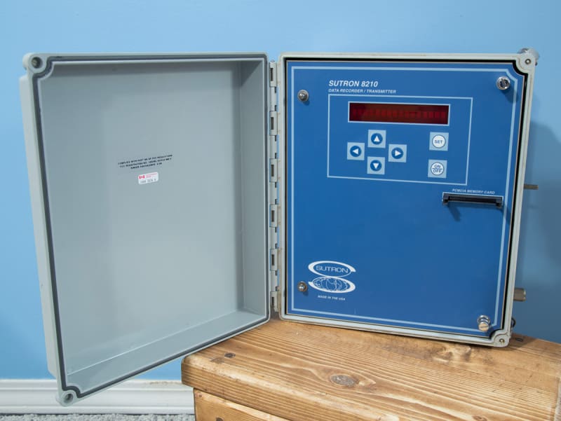
Most of what I have learned about anti-aliasing in ADC inputs involves filters built into the ADC, or oversampling, and other such strategies that focus on changes to the system logging the data. I'm stuck with a datalogger which I'm not not able to modify for this supposedly simple project, but I've got too much aliasing going on. The external circuit that transforms the input signal to the scaled signal that the datalogger can read is the place to fix this, and seems to be the source of the problem. For those interested, here is the datalogger:

Specifications
A neighbour of mine has made spot-measurements of his house voltage and is concerned about the safety of appliances in his house. He tells me he has seen readings higher than 130V, which is outside the allowable variation by local utility regulation. We want to record some evidence of our own, to understand the problem better, before pursuing the matter with the utility company or paying a consultant that the utility will respect. My goal is to provide the datalogger with a DC output about 4.0 volts which is scaled to the input voltage, taken from the 120VAC main power line. If the line drifts up to 130VAC, then the DC signal should rise from 4.0 to 4.3. The datalogger can re-scale the data, but it doesn't seem to deal with ripple very well.
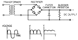
To make the scaled DC signal, I made a simple linear DC power supply circuit with no regulation. The AC is stepped down to about 4VAC through a transformer. The output AC is turned into DC with a full-wave bridge rectifier. Across the rectifier I have connected a 10uF capacitor and a 1k resistor. I believe this provides a DC output that will "follow" fluctuations in line-in AC voltage in a linear proportion.

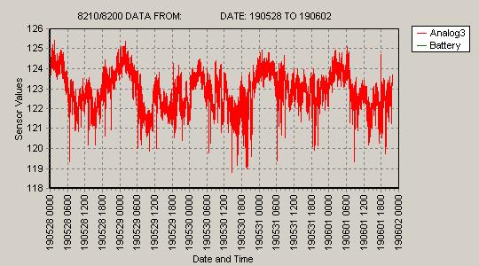
I believe that aliasing is the problem because my digital multimeter gives readings that wander up and down, and I've hooked the circuit up to the datalogger and get the same result. Meanwhile the needle on my analog meter stays steady as a rock if I measure the same thing. The true RMS DMM readings wander up and down by 10%, so I do believe the sampling is the problem. Both the datalogger and the digital multimeter behave the same way. Simultaneous measurements of AC or DC voltage with my analog meter shows all steady. I can't change the sampling rate of the DMM or the datalogger.
I have already increased the capacitor from 1uF to 10uF with no measurable effect. Should I try more?
Is there a way to filter or smooth out enough of the ripple that I can limit the aliasing to 1% (0.05VDC)?
Is there a different circuit that will do what I want better than the linear power supply?
No one believes the theory except the one who developed it. Everyone believes the experiment except the one who ran it.
STF

Specifications
A neighbour of mine has made spot-measurements of his house voltage and is concerned about the safety of appliances in his house. He tells me he has seen readings higher than 130V, which is outside the allowable variation by local utility regulation. We want to record some evidence of our own, to understand the problem better, before pursuing the matter with the utility company or paying a consultant that the utility will respect. My goal is to provide the datalogger with a DC output about 4.0 volts which is scaled to the input voltage, taken from the 120VAC main power line. If the line drifts up to 130VAC, then the DC signal should rise from 4.0 to 4.3. The datalogger can re-scale the data, but it doesn't seem to deal with ripple very well.
To make the scaled DC signal, I made a simple linear DC power supply circuit with no regulation. The AC is stepped down to about 4VAC through a transformer. The output AC is turned into DC with a full-wave bridge rectifier. Across the rectifier I have connected a 10uF capacitor and a 1k resistor. I believe this provides a DC output that will "follow" fluctuations in line-in AC voltage in a linear proportion.

I believe that aliasing is the problem because my digital multimeter gives readings that wander up and down, and I've hooked the circuit up to the datalogger and get the same result. Meanwhile the needle on my analog meter stays steady as a rock if I measure the same thing. The true RMS DMM readings wander up and down by 10%, so I do believe the sampling is the problem. Both the datalogger and the digital multimeter behave the same way. Simultaneous measurements of AC or DC voltage with my analog meter shows all steady. I can't change the sampling rate of the DMM or the datalogger.
I have already increased the capacitor from 1uF to 10uF with no measurable effect. Should I try more?
Is there a way to filter or smooth out enough of the ripple that I can limit the aliasing to 1% (0.05VDC)?
Is there a different circuit that will do what I want better than the linear power supply?
No one believes the theory except the one who developed it. Everyone believes the experiment except the one who ran it.
STF

![[wink] [wink] [wink]](/data/assets/smilies/wink.gif)
