Continue to Site

Eng-Tips is the largest engineering community on the Internet

Intelligent Work Forums for Engineering Professionals

  • Congratulations IDS on being selected by the Eng-Tips community for having the most helpful posts in the forums last week. Way to Go!

Deflection Of A Mass Due To Centrifugal Force

Daparojo252

Mechanical
Mar 25, 2015
12
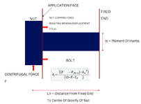
I am trying calculate the theoretical displacement of a mass that is fixed at one end, the other rigid due to a centrifugal force acting on a mass.
Where the other end is rigid, it subject to a tightening load against the application face, hence the centrifugal force, F has to overcome the force acting on the Nut due to tightening and friction to create the displacement. FF0.15.

Please see the file, and please comment if I can improve on this.

1743760233193.png


Thanks in advance.
 
Replies continue below

Recommended for you

Don't know if this is of any help. It hasn't been checked and it was to do with a different post some time back, but it may give you some ideas.
 

Attachments

  • Bolt Socket Pa BM PL.pdf
    112.5 KB · Views: 4
Per your drawing, the clamping force only affects displacement forces in the axial direction of the fastener. Your F would tend to cause displacement perpendicular to that axis, so that's resisted mostly by friction, isn't it?
 
If friction is not overcome, then you can effectively assume the mating surfaces of the nut and clamped material are bonded (or fused). Then the force traversing the interface will enter the clamped material, causing a diminishing shear displacement through the thickness and (increasing shear area with depth) and a linearly increasing bending moment (I increases with depth). You could assume the force propagates into a cone shaped material, at an angle of 45 degrees. That angle could differ. An angle to use could be the same as that used to encompassing the clamped material when calculating the compression stiffness used in preloading calculations. You will have two load paths acting in parallel (same shear displacement and rotation due to bending), the clamped cone and the bolt (assuming different materials, i.e. E and G).

If friction is overcome, then you'll have a state of sliding friction. A number of stress conditions will be introduced. The bolt head will slide, putting the bolt shaft into bending (assume S shape), shear and tension, whilst, at the same time, the clamped material will see compression and shear due to sliding friction. This is assuming no bolt head rotation and there's clearance between the bolt and the hole. A state of equilibrium will occur, where the work done by the displaced force equates to the introduced internal strain energy. Don't forget, the friction will aid you!

Sounds like an interesting problem!
 
Last edited:
Sounds like an interesting problem!
Possibly, but as stated in the OP, a constant force isn't likely to do much, since it has to have a shear component to do anything; otherwise, the surface, through friction, will simply carry the nut along for the ride. Only through mismatched phase, i.e., nut going north, while substrate goes south, is there likely to be anything interesting happening.
 
I believe that you have accurately modeled the deflection of the bolt as a guided cantilever beam. So I believe the equation you set up is accurate. However for the typical size of bolts and nuts versus centrifugal forces I don't think you would overcome the friction force (due to bolt tension - nut tightening) with the centrifugal force so you will not have any deflection of the bolt. Also the bolt hole in the Application Face would need to be slotted for any deflection of the bolt to occur.

Ln would be the distance between the Application Face and the fixed end of the bolt as this is the length that takes the shape of a guided cantilever beam when bending. Anything to the left of the Application Face does not exhibit bending during deflection, If you consider the Application Face rigid.
 
Last edited:
Just a pointer, you may think it's irrelevant. The joint is a preloaded bolt with material being clamped in the middle. If the clamped material was removed and a centrifugal force was applied, the nut would move vertically (assume zero rotation, fixed - fixed deflected shape, as though the mat'l was there). By the nut moving, wouldn't the new length of the bolt (from the fixed end to the underside of the nut) be shorter than the original length? With the clamped material in place, the shortening of the bolt length would be resisted by the clamped material? If the shortening of the bolt length was resisted, the clamped material would exert a reaction load on the underside of the nut, putting the bolt into tension + bending, and the bolt / nut would exert an additional compressive reaction on the clamped material. If this was to occur, the nut deflection would be much less than if the clamped material wasn't there. This is neglecting the friction force, which would reduce the nut deflection. I could be wrong, and I'm missing something. But that said, assuming the clamped material was not there would be conservative from a bending / deflection point of view, for the bolt (but no tension).
 
I just don't get this, but maybe that's me. To have a centrifugal force, something needs to be spinning or moving. What in this set up is fixed, and what is moving?

Maybe a picture of what this thing looks like overall would help?
 
Thanks you for the input, it's appreciated.
The application is made up of two flanges, with Nut on each end of the Bolt.
Rotation is around 3900 rpm and can be for a Bolt from M36 to M90 (so not so small, but large masses & centrifugal loads).
I always try to reduce the Nut mass to limit defelection and bending, and as Stress_Eng points out, the Bolt is subject to Bending & tensile stresses.
Dynamic loads correct. Should it not be dynamicly balanced at that rpm. Centrifugal force is no joke. Should it not have an added
Locking mechanism like thead adhesive and or lock washer?
 

Part and Inventory Search

Sponsor