Continue to Site

Eng-Tips is the largest engineering community on the Internet

Intelligent Work Forums for Engineering Professionals

  • Congratulations KootK on being selected by the Eng-Tips community for having the most helpful posts in the forums last week. Way to Go!

Design advice 3

Status
Not open for further replies.

Tuman_1232

Aerospace
Oct 7, 2017
20
Hello everyone,
I design some sort of one direction motion mechanical lock (see attached picture).
The green part leaves free move in X direction and jams otherwise.
It's my first time of this kind of projects.
Did anybody finish something similar to it?
On what should I pay attention?
Thanks in advance
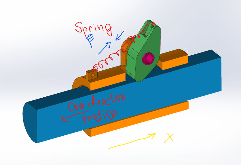
Annotation_2020-01-20_131304_ouln2i.png
 
Replies continue below

Recommended for you

Well forces and friction coefficient between your pawl and the bar / rod is the key issue here. How they are affected by different materials, contamination ( water, oil, grease etc) or wear on the pawl caused by erosion as the bar moves over time.

Plus the bending forces on your pin and its mounting could impact the design.

However this looks fairly simple and in common use so it definitely works to a certain extent but is dependant on friction between the two parts. loose or reduce friction and it won't hold the bar in position so not really a fail safe method of working. I wouldn't want to work underneath it let's put it that way.

If the bar or rod has notches in it then it becomes more like a ratchet device. Much stronger, but needs grooves in the bar.

Remember - More details = better answers
Also: If you get a response it's polite to respond to it.
 
Depending on forces involved and materials of construction, there could be dimpling on the shaft and/or galling on stop dog. What supports the blue shaft as it moves through the orange bore - this is a possible wear/gall location.
 
Add adjustability to your design, unless you are 100% certai, everything will be perfect and never wear out.
 
Consider a torsion spring rather than tension spring.

The orange piece will be expensive and difficult to machine. Will need to remove a lot of material from a piece of solid stock to make that out of one piece.
Is there a functional reason that the outside needs to be cylindrical?
 
Look for ways to reduce part count and precision, simplify assembly and use as well.

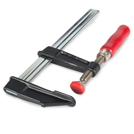
This bar clamp eliminates the cam, pivot and spring
bar_clamp_wdr83o.jpg


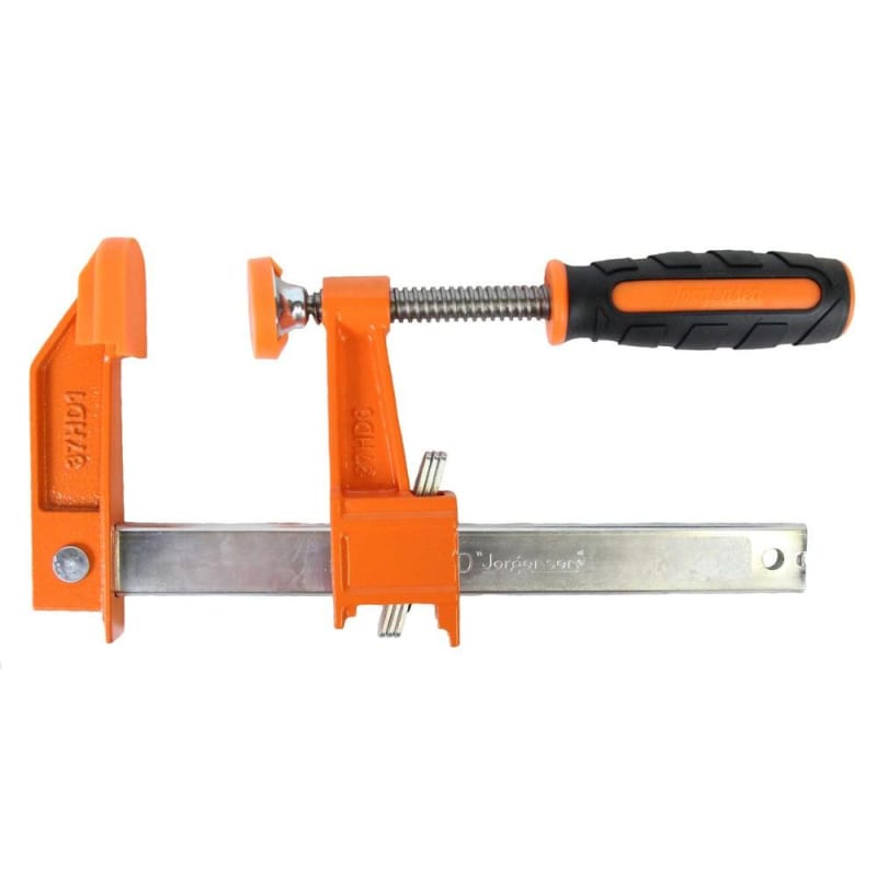
This bar clamp eliminates the spring and pivot, and the cam elements are low precision stampings.
bar_clamp_2_pjoaad.jpg


Theres lots a variations on this mechanism. Some will be better or worse for your application or production capabilities.
 
Ilya_Sh:
You have already milled the top of the shaft flat. Instead of that, mill a flat bottom, square shouldered groove, in the top of the shaft to fit a std. piece of rack bar stock (like a rack and pinion or ratchet). Fix this bar in the groove longitudinally, at some interval, and shape the pawl to fit the rack teeth. Then you potentially have a positive lock at regular intervals.
 
TRIZ wins for being older and nearly as vague.
The clutch equipped orange painted Jorgensen bar clamp has a spring to initiate the grip. I have a bunch of them.

There are a ton of one-way grip mechanisms, such as the metal tab on the rod of a screen-door closer.
 
Dave TRIZ looks cool. At Buff state we looked mostly at american scholars and work of creativity, TRIZ was mentioned only in passing, but I'm gonna take a closer look now.
 
Status
Not open for further replies.

Part and Inventory Search

Sponsor