Eng-Tips is the largest engineering community on the Internet

Intelligent Work Forums for Engineering Professionals

Design Feedback Requested - Moment Post Base 4

Status
Not open for further replies.

XR250

Structural
Jan 30, 2013
5,202
0
36
US
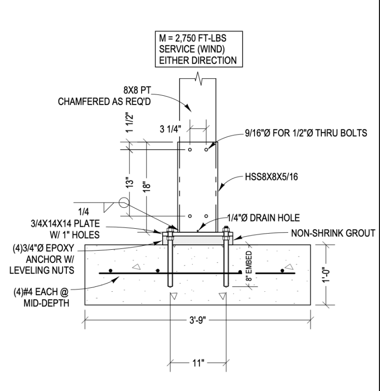
This is a design I want to try out with a contractor on a covered pavilion project and hope to use it going forward on similar projects that are flagpoled.
Please do not respond with "Simpson has a moment base" We don't want to use that and it has limited capacity and stiffness and it needs to be set prior to placing the concrete. We also have looked at Perma Column but it has too many issues to use.
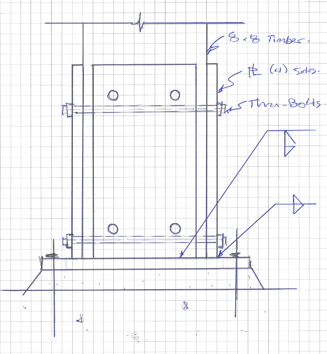
Would possibly like to substitute the bolts for a bunch of 1/4x3" Simpson SDS screws as trying to find the other side of an 8" long drilled hole is hard and they will end up wallowing it out. I am hoping bearing on the walls of the tube will be doing most of the work anyway (as long as it don't shrink too much)

Have at it...

Shoe_t80epc.png
 
Replies continue below

Recommended for you

1) Where's grade? I'd want to use this to keep the wood above grade. That's a lot of work and expense to have a post that will likely rot in less than 20 years anyway. (Maybe less than 10 in some environments.)

2) I'd figure out a way to elevate the post an inch or so off the bottom. It will increase demand on your fasteners, but it will greatly improve the life of the post if it is able to dry on the bottom. It also allows you to move your drain hole up a bit and out of the way of the weld (unless you intend to interrupt the weld to get the drain hole flush with the base plate).

3) Going to some sort of screw is certainly better than bolts. I'd design them for moment, uplift, and supporting the column (unless you have them put some sort of tabs or other means of reliably supporting gravity loads) as I don't think you can rely on firm contact. You'd end up with too much sway with any shrinkage, and there will be shrinkage. And with a wall that thick, you won't be pulling the tube in tight if you're using screws.

4) Isn't it a 'best practice' to taper the grout outside the baseplate? I thought that came up recently. It's a "how we've always done it" sort of item that I hadn't bothered to question before then, but I think there is a reason.

EDIT: 5) Probably want some sort of flashing to minimize water running down the post and into the gap around the edge.
 
XR250, some possible issues I see:

[ul]
[li]getting the post in the sleeve is a pain. the inside dims on an HSS never work out nicely for sleeving. You have a slight gap with your 8x8 (assuming 7.25" square) on the inside clearance, except at the corners where the timber fouls the steel. You'll need to chamfer the corners. Likely get a tight fit in some spots with small gaps in others.[/li]
[li]you have a drain hole at the bottom but I think there is still potential for this to hold moisture and invite rot.[/li]
[/ul]

Preference would be to replace the HSS with (4) side plates. Gives the wood some more room to breathe and also gives you more control on the inside clear dimensions of the base. Weld access might require a different weld detail on the 4th plate to be installed.

base_detail_melwb8.png
 
I've contemplated this same detail before, and I agree with the comments above. In terms of longevity of the wood, I would prefer an alternative detail which minimizes contact area between the wood and steel (where water/moisture can get trapped and isn't able to dry out). I think I would prefer a detail with 4 steel side plates as shown above, with the plates only being as wide as necessary to resist the required moment.

Any steel you use should probably be galvanized.

If some things I've heard and read here are true, be careful with the epoxy anchors. Apparently, most get installed incorrectly, so you might want to require testing.

For maximum longevity of this, some sort of stand-off at the bottom is perhaps a good idea (as phamENG notes).
 
We've used a double angle detail where two equal leg angles on opposite diagonal corners of the wood post are embedded into the footing and extend up the two side corners of the post...maybe 2 or 3 feet.
Then we use either through bolts or large lag screws to fasten the angles to the wood.

The tricky part is fabricating an angle assembly that has cross tabs (buried in the footing) that keep the two angles at the proper distance apart and allows for the whole assembly to be plumbed before concrete placement.


Hmm...I wonder if you could mix JAE's double angle design with yours, XR250.

You don't want to have to set it before the pour, so lose the embedded portion for a base plate. Then, weld a square plate the size of your post between the angles 1" above grade with a large hole in the middle for drying of the end grain, and have it extend up the 2 or 3 feet to be attached to the column. Chances are a pair of 4x4 or 6x6 angles will be more than enough to act as a column below the wood.
 
I like CANPRO's suggested modifications because it helps mitigate issues with trapped water and drainage, and it allows some access to the base of the wood post for inspection for deterioration in the future. Adding raised platform on the inside with lots of drain holes drilled in it would be nice, but would add substantial fabrication and and cost probably.
 
Thanks for the feedback everyone.
I'll try to address the majority of the common concerns.

I think I will cast a 3 1/2 inch tall by 18x18" thingy on top of the footing to keep the steel completely above grade.
The contractor does not think inserting the post in the tube will be an issue. Chamfering will be required and maybe some sanding.
He wants to try this design on this project.
Sloping the grout - makes sense but I usually don't see that
This will be used on covered structures(roof) so it will not be getting wet like a deck. I will add a standoff in the bottom though.
I don't think rot will be an issue the same as posts embedded in a lug of concrete.
I'd like to get SDS screws to work as has been discussed.

 
gte447 said:
Adding raised platform on the inside with lots of drain holes drilled in it would be nice, but would add substantial fabrication and and cost probably.

I don't agree. Easy enough to drop a loose 6x6 steel plate in there and drill a few holes. I would argue this design is cheaper than all of the alternatives suggested.
Materials may be more, but fab labor will be less.
 
Installation of epoxy anchors has been problematic for some of our bridge projects, to the point where we no longer use them in tension applications. The holes have to be thoroughly cleaned, and the epoxy has to be mixed well, neither of which happen on a consistent basis.

I recommend using cast-in anchors with a template to keep the alignment correct.

If you're using leveling nuts, the grout will not carry much of load, and can be eliminated. If you keep the clear distance from the leveling nuts to the concrete less than 1 bolt diameter, the bending in the bolts (due to horizontal shear) is negligible, and can be ignored (per the AASHTO sign spec, anyway, and I think AISC, as well). That is how we do all our poles, from the 30' light poles, to traffic signals, and the big high mast light towers.

All of our pole designs are governed (by a large margin) by fatigue at the pole to base plate welds. If you will have a large number of cycles of stress over 3 ksi, I recommend reviewing Chapter 11 of the AASHTO LRFD sign spec for detailing that connection.
 
How do you finish this? Wouldn't it better to just use HSS column the whole way? This does not look very appealing to me. If you do cover it up with stone veneer, it will rot even more?
 
DoubleStud said:
How do you finish this? Wouldn't it better to just use HSS column the whole way? This does not look very appealing to me. If you do cover it up with stone veneer, it will rot even more?
The steel will be painted. The arch. approved it.
Could use HSS the whole way but the contractor seems to want to do it this way.
If it was me, I would go steel all the way.
 
Achieving the necessary precompression with many of these "sandwich" methods will be challenging, and timber shrinkage will result in future slop in the connection regardless.

The single angle photo posted above is superior to any sleeving or sandwiching method. The timber post will be clamped tight, and can be easily retightened in the future if necessary.
 
If it will be galvanized you will need a bigger hole for venting. We often put a half circle (1-1/2" diameter) in the center of the HSS wall for this if it will be grouted (rather than in the base plate) as this allows for drainage after installation as well. Can your structure tolerate the movement that will happen before moment resistance engages after the post shrinks?
 
I think you will have issues with the connection overtime. The steel will not allow moisture to leave, so humidity will collect. The post will shrink and swell.

The post will never dry out in the socket. Even if it does not rain on it the timber will hold moisture as it is a sponge. If it cannot air dry, it will rot.

Can the 8x8 take the full moment alone? The stiffness difference btwn the timber and hss seems high so stress at the interface btwn the two will be high.

I do like JAE's design. Although I would use timber washers instead of homemade ones [bigsmile]

I have seen this detail work but it was in a pin column.
 
Thanks for the further feedback. I think I will re-think this.
Ironically, the owner and contractor are ok with just sinking the 8x8 in a lug of concrete.
 

Whatever you do, the wood will shrink perpendicular to grain, so if you want a moment connection, it will require retightening of the bolts. To my mind, that leaves out an RHS sleeve, screws, embedment in concrete...
 
Status
Not open for further replies.
Back
Top