Continue to Site

Eng-Tips is the largest engineering community on the Internet

Intelligent Work Forums for Engineering Professionals

  • Congratulations KootK on being selected by the Eng-Tips community for having the most helpful posts in the forums last week. Way to Go!

Design of Threaded Insert

noobokgbp

Mechanical
Jul 10, 2024
7
Hello All,

I am working on designing a threaded insert for a transmission casing where the original mounting hole threads were stripped. The casing material is ductile iron (6545-12), and the original damaged threaded blind hole has an M16x2mm thread, so the inner diameter of the insert must match this specification.

Since this is my first time designing a threaded insert, I'm unsure where to begin with the calculations and would appreciate any guidance. The only load case i am considering on the bolt threading into the insert will be from the transmission's weight and the specified torque for the bolt, which is 216 Nm. Is this correct? The transmission is side mounted, so the bolts are loaded in shear between the bracket and transmission.

Any help or advice would be greatly appreciated.
 
Last edited:
Replies continue below

Recommended for you

What is there to design? There are existing thread replacement inserts widely available, starting with helical wire inserts as needing the least material removal to install. They are all going to be stronger than the original thread. They have specially designed taps to meet the original thread requirement when the helical wire insert is installed.

The friction from the tension in the bolt should resist shear loads.
 
Hi
Firstly can I ask if you can provide a sketch or drawing of your situation and secondly you don’t say how the original tapped holes were damaged, was this due to external forces from the transmission?
What grade of bolt are you using and what are the mechanical properties of this iron and how is the insert secured to the casing?
 
I agree with 3DDave. Use an existing insert. Would be an expensive part to design yourself.
 
If you use Electric torque wrench, do not design according to 216Nm, its just a static torque, impulsive torque while tightening must be considered.
 
I agree with the others that there is no need to design an insert. There is a standard product line out there (Helicoil and others). There are 2 ways to go:
1. Use the insert that installs into an M16x2 thread, which gives a smaller thread at the insert ID. This will require a smaller bolt.
2. If you have the wall thickness available, use an insert with an M16x2 at the ID and tap a larger thread according to the OD of that insert and use the same bolt.
If you have indeed already chosen course #1, you are reducing the bolt diameter from the original design, then you ought to consider going to a higher grade (if available) to get some strength back. The Helicoil specs will tell you the new ID thread available and strength ratings. The torque is specified to achieve a certain bolt axial tension that we'll call F. That is your main concern. The formula T [Nm] = 0.2 x F [N] x d [m] can be used. The new bolt has to be capable of supporting the F tension value. A safety factor of 2 can be applied to ensure cyclic loading robustness relative to the static proof load for the bolt. The F value for the original design can be backed out by the same formula assuming you know the M16x2 installation torque.
 
Hello All,

Thank you for your responses. Going to answer all questions here.

We have tried Heli-Coils and they did not work, specifically because they were installed without a mag-drill or a CNC machine. So they were installed at an angle. We had to remove them and that further damaged the existing holes.

We tried to move over to other type of inserts like ez-lok (locked-in by pre applied loctite) or keenserts (locked-in by self-broaching tabs). These did not have the depth we needed. The depth of of hole on the M16x2mm is 25mm. the max size we could find was 20mm for ez-lok and 22mm for keenserts. for the keensert we are ok with losing 1.5 threads, however lead time is an issue. We cannot get them in time for shipping this and it is a machine-down order, so a customer is waiting for it.

Hence i am designing one and have limited knowledge about designing inserts and cannot find any standards to help with the design.
 
Hi noobokgbp

So how do you intend to fix these inserts into the existing hole? Thread, force fit or ???.
Depending on how you retain the insert will influence the calculations required.
 
securing either by force fit or self-broaching. Possibly welding around the top as well.
 
Well, I'm guessing that all the people who know how to design thread inserts work for the thread insert companies. I would start by getting this information:
1.) What are all the torque and force specs for the old M16x2 bolt?
2.) Do you have any spare wall thickness available in the transmission housing to form a new thread, possibly larger than M16x2?
3.) How much time do you have to get this insert design done?
 
Don't know if you can reliably weld ductile iron but and you fill the hole, drill and re-tap?
 
"We have tried Heli-Coils and they did not work, specifically because they were installed without a mag-drill or a CNC machine. So they were installed at an angle. We had to remove them and that further damaged the existing holes."

I suggest you learnt the wrong lesson for this experience. It's not that "heli-coils don't work"; I think the lesson is "properly install Heli-coils (rather than installing them at an angle ... lord knows how that happened) if you want them to work".
 
Hi noobokgbp

Right so your first task is to decide how to secure the insert, if by interference fit the interference should be such to prevent the insert coming loose under normal load conditions. Can you provide some drawings or sketches of the problem?
Currently none of here can see the details/ conditions you are working with and for the sake of giving you some proper assistance please provide some more detail if possible otherwise the guessing game starts and the thread ends up with 300+ posts none of which might help you.
 
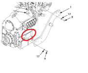
Due to the nature of the business i work for, even i do not have drawings, everything is tightly controlled otherwise i would have. Usually i get all my measurement from a portable CMM arm. this also takes some time. So i do apologize for the lack of information. The attached pictures are from field service manuals so i can share them.

The hole features highlighted in red are damaged due to many things that happened. This is where i am to put the insert i design. I have received lab results for the casing and i have cast iron for the housing. The other side of the TM has the same mounts and hole features (symmetrical), but they are not damaged.

Screenshot TM.png

Hopefully this helps a little more.
 
Once a hole is chewed out too much for helicoils then keenserts are the next step, but it doesn't matter what you do if the machining that is done is sloppy. Threaded holes are an intermediate precision mechanism that does not tolerate a great deal of error.

Matching the depth of the threads doesn't matter much. After 3 to 5 threads of engagement further threads offer no additional strength. When there is a large depth of tapping beyond that it is because the tap is tapered and the additional threads are to ensure that the taper goes beyond the necessary complete threads to ensure the mating fastener can enter the hole. A typical tap has 7 incomplete threads; in this case that is 14 mm. 5 threads is 10 mm. Thus a hole would typically be 24 mm deep. Your hole is 25 mm deep, which is an additional 1mm to give some clearance to prevent the automation from snapping the tap off in the threaded hole.

5 threads at 2mm pitch is 10 mm. A 1D (ratio of depth to diameter) insert is around 16 mm, for extra confidence, but recall one will lose about 1 turn at the top for the chamfer.

The good news for keenserts is you can use standard taps and those include plug taps that only need 3-4 threads (6-8 mm) of clearance. 8 mm + 16 mm = 24 mm, which your hole has depth for.

Hire a mag drill and very good machinist or you will be hiring and even more expensive qualified welder to try to braze a plug into the side of this who will expect that a mag drill and very good machinist drill out the big hole the brazed plug will require.
 
Hi noobokgbp

Thanks for the illustration, okay the problems you need to sort out are:-

If using an interference fit then you need to check the linear coefficient of expansion for both the threaded insert and the material the insert is mating with, because if there is any temperature rise involved during operation of the equipment, then this can cause the insert to come loose due to differential thermal expansion. Also the torque you have quoted appears to be about 90% of the maximum torque permissible for an M16 grade 8.8 screw which translates approximately to an axial load of 80 KN, so the internal thread of the insert must be capable of withstanding the shear stress generated by the 80KN force, similarly the interference fit between the insert and mating material must also be capable of transferring the 80KN force without any movement or slippage.
I am not sure if there are any external forces involved on your assembly but they also need to be taken into account over and above the bolt torque.

I agree with others you should use an off the shelf item and regarding lead time my response would be “ we never have the time to do it once correctly but we always have time to do it all over again”
 
Last edited:
Those look like load-bearing bolts. Unless there is an obvious root cause related to operator error, the strength of the repair is going to be crucial and with castings such as this, there may or may not be adequate remaining metal around it to support it.

I would consider if a complete plug and re-tap is possible. Maybe tap to M24, install a ductile iron plug, and re-machine the tap. Apply high strength locking compound to the M24 threads and then add another tapped hole or two (say M4) across the M24 threads in a couple of places and insert grub screws to further resist the plug from backing out.

Helicoils were your best option - properly installed, they are stronger than the original threads. But clearly this component is destined to be worse than original condition now.
 
1 - What is the OEM's recommended torque for the bolts/screws securing the bracket to the transmission case?
2 - Ditch the lockwashers.
3 - the faying surfaces on the bracket and the transmission casing must be flat within .005" and max 250 Ra µin.
3A - 80% contact minimum. 100% contact around the tapped holes.
4 - I don't think a mag based drill could accurately grab the transmission case directly. A fixture made of plate with a couple of long/tall drill bushings would adequately align holes even by drilled by hand.

5 - "The strength of most highly loaded bolts and studs is determined by the man with the wrench and not by the designer, the metallurgist, or the manufacturing processes."
 

Attachments

  • 1944000.pdf
    469.2 KB · Views: 7

Part and Inventory Search

Sponsor