Eng-Tips is the largest engineering community on the Internet

Intelligent Work Forums for Engineering Professionals

Design Strip For Irregular Flat Slab? 4

Status
Not open for further replies.

J189

Agricultural
Oct 7, 2019
29
0
0
AU
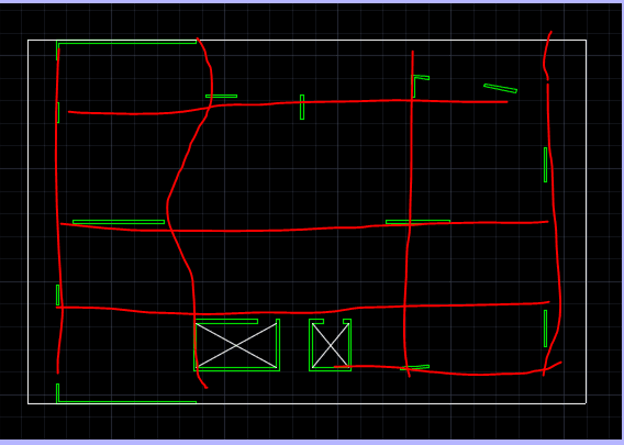
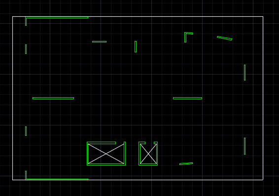
I have a flat slab with irregular supports. I want the reinforcement to follow the global x & y direction instead of principal moment direction.
So I am thinking having design strips passing each support but I find it very hard to arrange the design strips. Can anyone share your thoughts or if you can, provide your design strips say latitude for this one?

As these short walls have two ends, do I run two design strips through both ends? Can anyone please share some example of this kind of structure?

Thank you.
1221_oravik.png
 
Replies continue below

Recommended for you

I am using SAFE but happy to learn other experience from Ram Concept too. I want the strip to run along global x and y so running design strips from support to support will make the reinforcement follow principal moment direction (maybe that's what skew angle is for in Ram Concept? I am not familiar with Ram Concept but SAFE has no this option). Put that aside, theoretically, we run multiple design strip along global axes direction and make them pass each support although each design strip may run through one support only instead of linking support together?

Isn't design strip to average out the peak moment and as such we should run the design strip pass each end of walls, where peak moments generate?
 
Thank you very much rapt.
I notice that some walls have no design strip across in either x or y direction. ie. analysis results of some walls not used in the design strips?
 
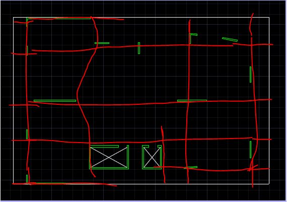
I did say it was a rough sketch.

There are a couple of extra short ones added at local walls.

This is actually a relatively simple layout. Your design strips have to give a load path to the supports and normally are relatively orthogonal, as your reinforcement will be. If you are analysing using FEM, it should be evident from the moment patterns.

design_strips_qztjdq.png
 
I was basing on orthogonal strips to suit orthogonal reinforcing patterns.

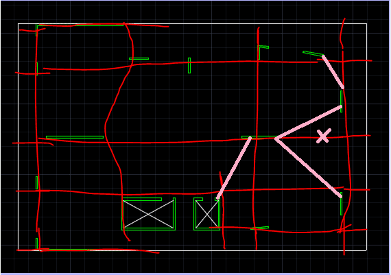
I disagree with the one where you have the cross, with a 45 degree support strip. I think the vertical one I have shown will take a lot of the load.

Same with the one into the core. I have shown a negative moment one from the side of the core. But I do not think it would be a full support strip as you have shown. I think the vertical one to the right of it will pick up most of the load from the slab panel to the right, based on relative stiffnesses of different areas and strips.
 
Another tactic to suggest.
Design strips as was stated above are simply working elements that average out peak stresses. A moment contour map in SAFE shows how high they spike at the columns.
You might try littering your whole plan with 4’ wide design strips, both ortho directions. Run each strip from support to support (even if it goes the whole floor plate).
Run the analysis then use SAFE to show where your moments are.
Good luck!
 
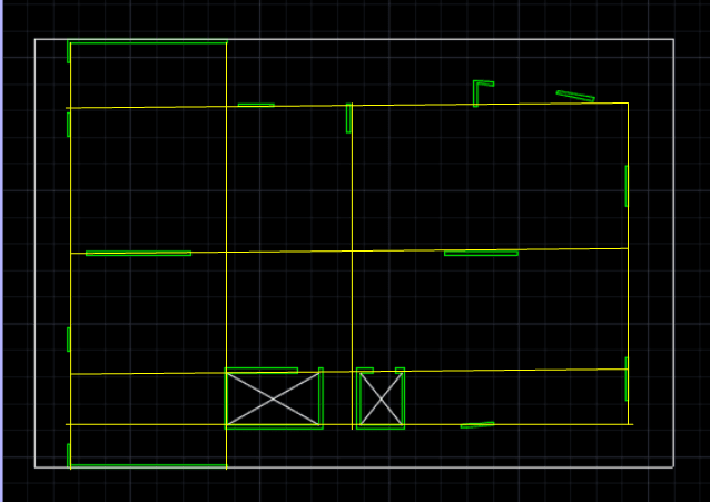
Thank you everyone. Sorry I didn't make it clear. What I really want to ask is, as I tried to make the design strip or rather reinforcement going in both ortho directions instead of support to support. Take the Y direction near the core wall as an example. Do I need to have multiple design stirp across supports as below? The reason I am asking this is like I said, the design strips are to pick up and average the peak moments.
12222223333333_c3ffji.png

If I don't make the design strip across the supports where peak moments generate (refer below as an example), then the design strip will not pick up the peak moment?
223555_ccdjzs.png


But if I do make these multiple strips then the strip will be too narrow and not much width to average the peak moment. What is your thoughts on this?
 
This is actually what confused me. Like you said, the design strip is to average out peak moments. Then how can I arrange 4' wide design strips? Don't I need to make sure that the design strips pass the supports, where peak moments are? But as I want to make them in ortho directions, I cant link strips from supports to supports even there are very small offsets. Instead, I have to arrange my strips in a way that they pass every support in ortho direction, making them very narrow sometimes. So what do you do? Do you first look at the moments of each support and ignore the near ones that have lower moments? (ie just run the strips across the support that have higher moments than the ones nearby?). What about M12?
 
If I have skewed strips then the reinforcement designed won't be in ortho directions, correct? I don't think SAFE offer skew angle feature like Ram Concept does. Then How do you sort this out?
 
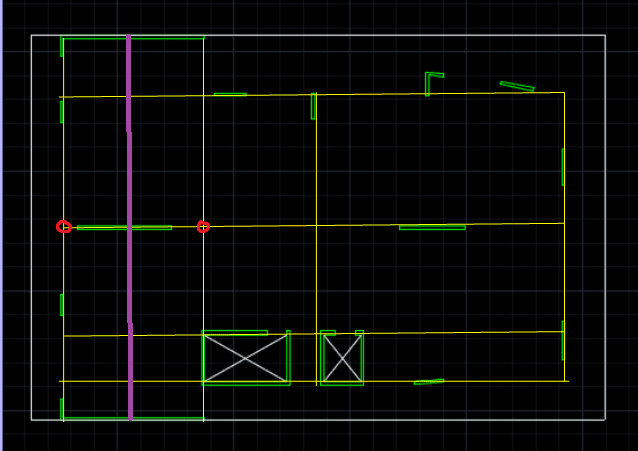
I am using your example to show my concern. I have circled two area that your longitude strips do not 'connect' to the support where max peak moment will be. So what will happen is the design stirp will pick up the moment where circled are and reinforce the whole strip based on the peak moment on locations circled instead of the the locations within the support (internal wall going in x direction) that have higher peak moments. Will this be okay or do I need an extra strip shown in purple? If I run the strip like what rapt did then it is not in ortho directions..
s_paad4q_brqsu6.png


If I am right about this, then looks like I need to have too many strips...
 
Do you guys generally reinforce strips differently? We used to but now typically provide the same bars throughout after an FE design since rebar is so cheap here. Its easier for the guys to install, easier to walk on, easier for us to inspect along with a lesser risk of something being missed.
 
I was showing design strips as I would for a PT design to provide a logical load balance tendon pattern. Or for an RC design when doing without FEM. But those strips can still vary from a straight line as my rough sketches showed. They can then have "transfer" strips to pick up strips that end up well away from supports, and even short "negative moment" strips as I showed on my second layout. Some design codes suggest 10% variation in straightness does not require extra analysis.

Using FEM, all you have to do is provide the othogonal reinforcement requirements at each point in the design as required by the distribution of the moments over the slab. By providing the X and Y reinforcement in each direction the X/Y capacities combine to provide the principal moment capacity required to account for non-orthogonal principal moments at each point.

As MIS... suggested, if there is not a large variation of reinforcement requirements across the slab, I would simply supply top and bottom mats of reinforcement to cater for the maximum.

If there are a few peak areas requiring a lot more reinforcement than the general slab requirements, base the mat on a lesser value and add extra bars for those peaks.
 
Status
Not open for further replies.
Back
Top