Continue to Site

Eng-Tips is the largest engineering community on the Internet

Intelligent Work Forums for Engineering Professionals

  • Congratulations KootK on being selected by the Eng-Tips community for having the most helpful posts in the forums last week. Way to Go!

Design trailing arm suspension 2

Status
Not open for further replies.

Spanish Wells

Agricultural
Jul 25, 2020
39
Hi to all; I wonder if someone could help me please ?
I'm designing / building a trailer using a trailing arm suspension system. My problem is to design the arm to accommodate the torsional stress involved.
The wheel / tire is 32" diameter, 10" wide.
Static load of 4,000 lbs per tire.
The stub axle(inc brakes) will be attached to an arm approx 20" long from axle center to pivot point.
This arm will be a "bell crank" transferring suspension loads to an air bellows suspension.
My problem is to specify the section of the arm to resist the torsion loads.
I want the arm to be as thin as practical to minimize the overall width of the system.
My thoughts are to flame cut the arm/bell crank from A36 structural plate of the appropriate thickness.
Could somebody help with the appropriate formulae so I can look at various sections of the arm,
for example: what width would I need for 1" plate, or 1.5" plate, etc.
I'm thinking I could build a table using Microsoft excel to include all the variables such as: load, g force, twisting moment, length of arm, material thickness, material width, mechanical properties of the steel, etc and play with the section of the arm to give me a good solution.
Appreciate any help.
Bob
 
Replies continue below

Recommended for you

How could you anticipate the structural engineer understand a mechanical/automotive setup without a sketch! Good luck.
 
Ditto to the above. Although I'm not so sure a sketch will help, either.
For the immediate issue, if this is a prismatic member loaded in torsion, refer to Roark's Formulas For Stress and Strain and you can find means to calculate the torsional stresses. Combine that with bending and shear stresses via the failure theory of choice.
The bigger issue with vehicle design is not knowing the loads in the first place. I'm not aware of any standard that tells you that you should design for 2 or 3 or N times the static weight to allow for dynamic loads. Or alternatively, that everything should be designed to hit a curb or "standard pothole" at X mph.
In a fatigue situation, using flame-cut A36 plate may not be the best approach either.
And in commercial vehicles, lighter weight translates into greater payload capacity so "when in doubt, make it stout" is not always the desired approach.

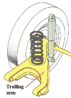
Googling the trailing arm suspension gives lots of images, one here, if that helps:
TrailingArm_dgapd4.jpg
 
Well thanks for the comments.
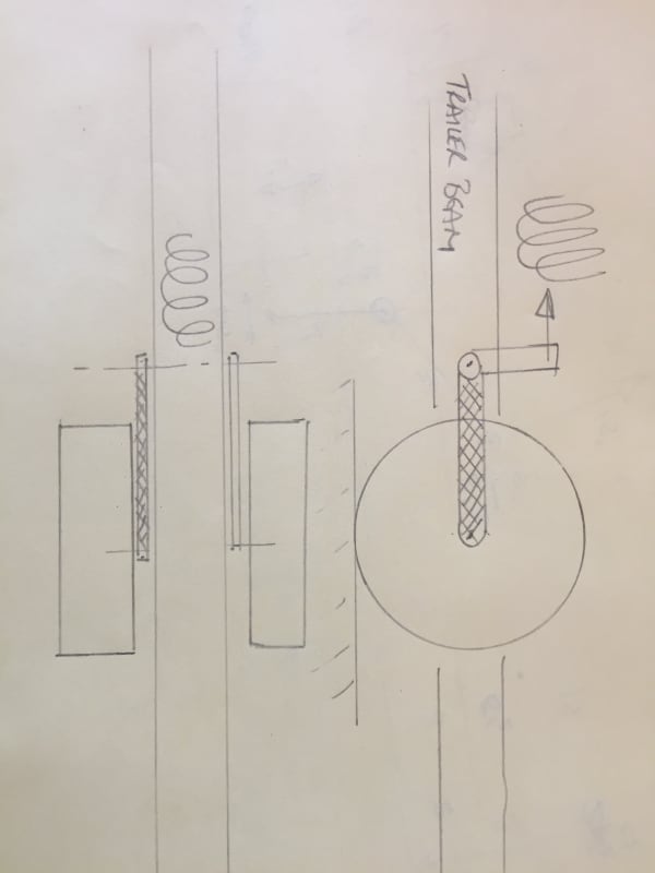
Here is a "sketch" to show the principle. The member I'm concerned about is shown "hatched".
The sketch shows just one side of the trailer.
Weight is not too big a concern for me in this situation.
If I can get an appropriate calculation, I can play with 2 or 3 "g" and see the effect on arm.
I'm thinking A36 plate as it is readily available and easily fabricated.
IMG_2705_1_m4i4na.jpg
 
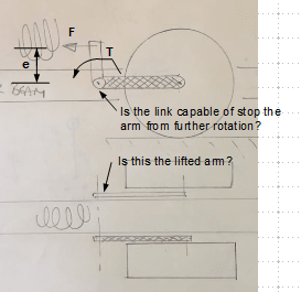
:) JS is correct, I am no less confused than before. I think more details/clarification are required to draw to-the-point responses. Allow me to have a try, is this what you meant?

image_vnnqru.png
 
Retired,
My apologies for not being clear !
The trailing arm, which I have shown hatched, pivots about the point identified by your arrow.
This link will be a "bellcrank,transferring the load to the spring which lies in the horizontal plain.
My concern is defining the necessary section of the trailing arm, to withstand the twisting moment from the wheel / stub axle. My aim is to make the trailing arm as "thin" as practical, to keep the overall width to a minimum. The trailing arm will be a rectangular section.
There will be a crosslink between the two bellcranks to transfer the total load to the spring; "F" in your sketch.
Hopefully clear ?
Thanks
Bob
 
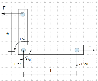
Does this look like and make sense? If so, you shall check bearing of the pin hole, tension on the net section, shear on the gross section, and flexural stress (δ = M*y/I ± F/A). Note F can be in reverse direction, then the horizontal arm is in compression, you have to check plate buckling stress.

Note that you shall provide fillet at the inside corner to avoid stress concentration; and shall provide a beefy safety factor as dynamic force and fatigue are involved.

image_efwgje.png
 
Retired,
You've got the concept, schematic.
I certainly will need to consider the bearing surface for the pivot, and also the filler between the vertical and horizontal arms, no problem.
However my concern is trying to establish the stress in the horizontal member "L" in your sketch, due to torque effect from the stub axle.
As stated earlier, static load about 4,000 lbs on the wheel.
Centerline wheel to centerline of trailing arm "L" = approx 7 inches.
The section of "L" would be a rectangle. I'm not understanding how I calculate the stress in this member due to twisting moment of the wheel.
Thank you.
 
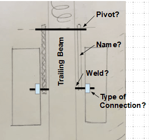
Can you answer the questions below (from top down), so we might be able to be on the same page.

image_crilha.png
 
Retired
Pivot - poly bushings of sufficient diameter and width
Name - Trailing arm
Stub axle - 3" OD welded to Trailing arm
I don't understand what you mean by "type of connection". I have not yet decided whether to butt weld stub axle to Trailing arm, or whether to bore a hole in trailing arm to pass stub axle through and weld both sides.
Thank you
 
I'm not sure why i am jumping in on this other than I am trained as an M.E.
A flat plate is not a great choice for a trailing arm. It is very inefficient at resisting torsional or lateral axle stub loads.
Maybe somewhere in Roark's there are formulas for this.
A tube or pipe section would be a better choice.
 
I agree with xr250.

A solid flat plate is terrible in torsion compared to a circular or square section tube, but they are of course a little wider than a flat plate.

The other option here is to place your flat plate thing on both sides of the wheel eliminating the torque, but of course makes it more difficult to take the tyre off...

Also is this wheel braked? Are there going to be alternating forces and torque effects on the stub axle from a brake?

Really not sure why you're literally trying to reinvent the wheel here. There are multiple off the shelf suspension designs for trailers.

does that main beam need to be directly in line with the axle stubs? what not use an axle to connect both wheels?

Remember - More details = better answers
Also: If you get a response it's polite to respond to it.
 
Thanks for the input.
I'm working on a boat trailer.
The boat weighs 24,000 lbs, 42 ft long, 13' wide and 12 feet overall height.
My design is like a "tuning fork". The frame will be two 10" sq tubes,spaced about 6 feet apart, running full length.
Eight of these suspension / axle set-ups, two each side of each each frame member for a total of eight.
Total load capacity 28,000 lbs. Yes there will be brakes on each wheel.
Detachable cross members which allow the trailer to be driven under the boat, while it sits on blocks.
The suspension will be air bags / bellows as seen on highway 53' van trailers. This gives me the ability to raise trailer to lift the boat.
The option does exist to use a solid axle that would run beneath each trailer frame, however this raises the overall height of the trailer frame. I need to keep the boat as low as possible for bridge clearances, etc.
I'm limited to 102" trailer width, ideally, to avoid need for permits when trailer is empty.
Minimizing the width or thickness of these trailing arms will maximize the space available between the tires, in a limited overall width, ie:
Tires 9.5"" wide x 4 =38"
Frame members 10" x 2 =20"
Tire clearance to trailing arm 1"x4 =4"
Trailing arm arm clearance to frame 1/2" x4 =2"
Thickness of arm say 2" x 4 =8"
Total of above =72"
Subtract from overall width of 102" gives 30" between tires. This is sufficient for the keel of the boat, but I also need to be able to change a tire if necessary. For each additional inch in section width of the trailing arms, I loose 4" of clearance between the tires.
I want to maximize this space, within the 102" limit.
I take the point that a piece of flat plate is not the best for torsion. I'm looking for the formula so I can evaluate different sections for the swing arm to minimize this thickness.
It may be that the required section of the swing arms does not allow me to stay within 102" overall width and still maintain sufficient space between the tires.
As in all design work there are compromises necessary....
Appreciate the interest and help.
Bob
 
Your constraints make sense. Makes me think of my VFR800 motorcycle which has a single side swingarm that is a pretty beefy, welded up, tube section.
How much travel does the suspension have?
Would it be possible to slot and reinforce the tube and run and axle through?
Try Roark's Formulas for Stress and Strain. Might be some info in there about flat plate torsion.
 
Thanks XR,
Operating range on the air bags is 8". But probably more if I let most of the air out to lower the suspension for loading. Depend on the lever ratio, suspension movement >10", so that precludes a reinforced slot.
I'm beginning to realize that the thickness of the trailing arm may need to be a least 2".
If I'm forced into a thicker section and can't get sufficient clearance between the tires in the middle, I may not be able to meet my ideal of 102" overall.
This may not be the end of the world. It will remove a major constraint in the design, improve stability of the trailer and allow more room between the tires. I believe the next "sweet spot" is 120" overall width.
This would allow a box section trailing arm, of perhaps 3" section width. Also structural hollow sections indicate improved stress capacity over A36 steel.
Once again, can someone help with the required formulae for a rectangular or square box section, please ?
Bob
 
I should stop to say anything that I don't have a clear understanding. However, I guess the torsion/torque is essentially has a bending effect on the trailing arm rather than linking it to "twist", so a flat bar should be able be designed to handle the task. The reason that I asked the "connection" to the tyre is that isn't that the source of torsion, other than the horizontal force shown on the sketch? I am trying to understand the setup and source of forces, and see whether it can be solved through simple mechanics. Please ignore my questions and comments, if they are far from the picture.
 
how does your design compare to JStephen's post ?

how does your trailer differ from the millions of trailers that are out there today ?

You roll the trailer down the ramp, the boat "swims" in, the rest is history ? Beams support pivoting "paddles" that'll conform to the boat's bottom.

or possibly you lift the boat onto the trailer ?

The trailer should consist of beams running under the boat. It sounds like you're trying to have stub axles, with an offset load. This'd create bending.

another day in paradise, or is paradise one day closer ?
 
Thanks Retired for trying to get it clear !
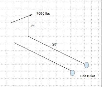
Think of it as a simple member, 20" long. This member lies in "X" direction.
One end is supported on a pivot, with support on both ends of the pivot.
The other end has a lever, firmly attached, that sticks out 6", in the "Y" direction.
At the end of this lever is a force, 7,000 lbs static, in the "Z" direction.
The effect of this force is to try to twist the member, resisted by the pivot.
I'm trying to calculate the torsional stress in this member, as a function of the force, distance of force from neutral axis of member, length of member, cross section of the member, be it a solid, rectangle, square or round tube. With an appropriate formula, I can consider various sections for the member, and calculate the stress.
I will have to include some dynamic loading, and also the bending load in the member. I'm starting to think tube maybe my best solution, be it round, square or rectangular section.
Thank you
Bob
 
I am with you up to this point. But confused on "One end is supported on a pivot (as shown), with support on both ends (where and how?) of the pivot". What kind of restraints the support provides? For true torsion situation, wouldn't it be T = F*e, and δ = Tr/I[sub]p[/sub]. Round bar is better fit to resist torsion, but how about the thickness constraint?

image_akfir3.png
 
Status
Not open for further replies.

Part and Inventory Search

Sponsor