Continue to Site

Eng-Tips is the largest engineering community on the Internet

Intelligent Work Forums for Engineering Professionals

  • Congratulations KootK on being selected by the Eng-Tips community for having the most helpful posts in the forums last week. Way to Go!

Design trailing arm suspension 2

Status
Not open for further replies.

Spanish Wells

Agricultural
Jul 25, 2020
39
Hi to all; I wonder if someone could help me please ?
I'm designing / building a trailer using a trailing arm suspension system. My problem is to design the arm to accommodate the torsional stress involved.
The wheel / tire is 32" diameter, 10" wide.
Static load of 4,000 lbs per tire.
The stub axle(inc brakes) will be attached to an arm approx 20" long from axle center to pivot point.
This arm will be a "bell crank" transferring suspension loads to an air bellows suspension.
My problem is to specify the section of the arm to resist the torsion loads.
I want the arm to be as thin as practical to minimize the overall width of the system.
My thoughts are to flame cut the arm/bell crank from A36 structural plate of the appropriate thickness.
Could somebody help with the appropriate formulae so I can look at various sections of the arm,
for example: what width would I need for 1" plate, or 1.5" plate, etc.
I'm thinking I could build a table using Microsoft excel to include all the variables such as: load, g force, twisting moment, length of arm, material thickness, material width, mechanical properties of the steel, etc and play with the section of the arm to give me a good solution.
Appreciate any help.
Bob
 
Replies continue below

Recommended for you

For the pivot, imagine a cross tube welded to the "member", with polyurethane bushes, and brackets welded to the frame.
Regarding the thickness constraint, I need to calculate the stress in different cross sections, to see if I achieve my thickness constraint within the 102" overall trailer width. If not I have to compromise on overall width and use a larger section for the trailing arm.
 
RB,
The "tuning fork" refers to the main structure of the trailer. Two pieces of 10" square tubing 40 feet long.
My concern is with the trailing arm, referred to as the "member" in post at time 17:01.
 
IMG_2707_1_aro5lw.jpg
 
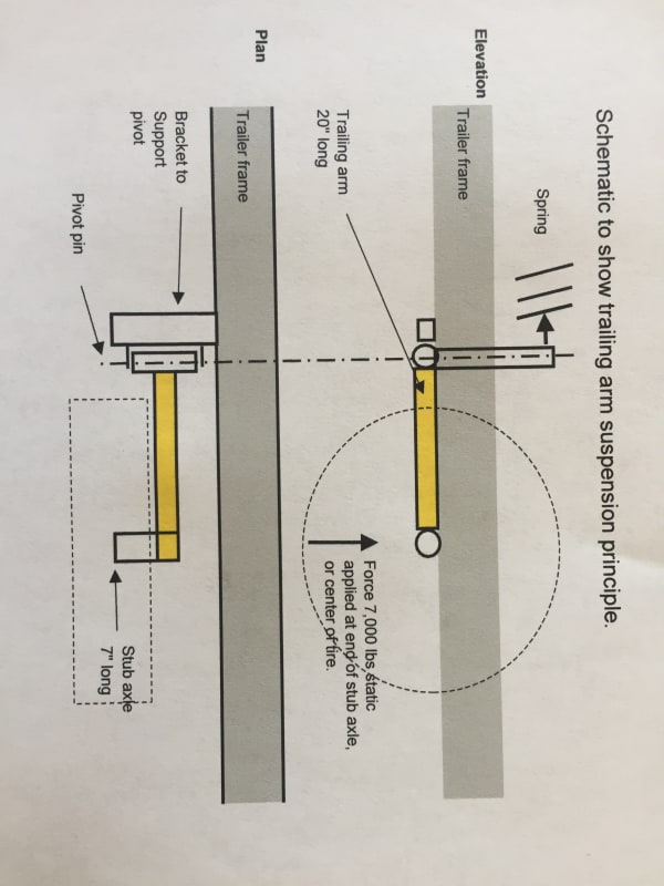
Hopefully the schematic I've just uploaded will be clear.
I'm concerned with the arm shown yellow in the sketch.
Not to scale, no bracing included etc. For the purpose of this discussion I'm just concerned with thr "yellow arm".
 
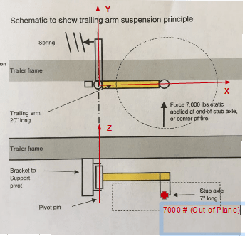
If this is correct, the short stub subjects to a bending moment of 7 kips* 7" = 49 kips-in. Then, this bending becomes torsion on the trailing (yellow) arm, assuming the brake pad is capable of restrict the rotation of the pivot. I don't think this assumption is correct though.

image_jxyuvc.png
 
Retired,
I don't think the rotation of the pivot or brake pads is the issue. The spring will resist the rotation of the arm around the pivot point.
The torsion in the trailing arm, yellow member is the issue.
 
The forces calculated is for the both of the bending on the 7" stub, and torsion on the 20" yellow arm.

image_qa0wjv.png
 
At 14 tonnes weight this is no laughing matter.

One of these perhaps?


There's zero chance of this trailer being allowed onto the public road.

If it's for transport with private land then you need to go brutal engineering and not try and nuance this. IMHO.

But we'd still like to see a photo once you've built it....

like this?


Remember - More details = better answers
Also: If you get a response it's polite to respond to it.
 
Littleinch
This is exactly what I was looking for, thank you !!!
So after a bit of toying with ideas, I went to the formula for round hollow bar.
I put in the following variables: I'm in the US, so Imperial units
Load 7,000 lbs x 2 for shock = 14,000 @ 7" radius = 8,200 ft-lbs
Tube outer radius 1.5", inner 1" (3" tube, 2" bore).
Shaft length 20"
Mod of rigidity 11.24 (Mod elasticity 29,000 ksi, poisson ratio 0.29, 1045 med carbon steel)
Results:
3" tube, 2" bore, 1/2" wall:
Max shear stress 23,200 psi
Angle twist 1.6 degrees.
Clearly a very stout member.

3" tube, 2.5" bore, 1/4" wall:
Max shear stress 36,000 psi
Angle twist 2.4 degrees.

3.5' tube, 3.0" bore, 1/4" wall:
Max shear stress 25,000 psi
Angle twist 1.5 degrees.

3.5' tube, 2.75" bore, 3/8" wall:
Max shear stress 19,000 psi
Angle twist 1.1 degrees.

This is exactly what I was looking for - Thank you.

Clearly I will not be able to achieve 102" overall width.
If I use 3.5" tube then the measurements will look like this, with a 120" overall width:
2 trailer beams x 10" = 20"
4 tires x 9.5" = 38"
1" tire clearance = 4"
1/2" trail arm clearance x 4 = 2"
4 trailing arms x 3.5" = 14"
Total 78"
Center clearance = 120-78" = 42".
Comments ?
 
Here are some similar designs available in the US:
22,000 lbs capacity: I believe this is also a trailing arm design. The load on each tire is about 6,000 (tire rating).

Go to "Gallery" and ses designs with open center of the trailer.
With a dual tire option, there must be enormous torsion generated in the suspension arms.

Once again, go to "Gallery".

Video of 16,000 capacity trailer
 
Every one use hydraulics.

Remind me again why you're trying to reinvent this?

Certifying a trailer for road use would hopefully be quite hard to do.

Remember - More details = better answers
Also: If you get a response it's polite to respond to it.
 
LittleInch
The hydraulics are there for the support arms, and in some cases to raise/lower trailer.
Yes I will incorporate hydraulics for support arms, but not to raise lower - I plan to use the air suspension for this feature.
Certification laws are a little different in the US. However, the design needs to be robust, etc, for all the good reasons.
Why am I doing this ? - because they are very expensive, I have access to the fabrication equipment and skills, and it is a very interesting project.
In my original thinking I was very concerned with the torsion in the trailing arm, therefore considered lots of fairly low capacity tires to reduce this. Now I'm able to calculate the torsion in the trailing arm, and after reviewing some of the photos I just posted, I'm looking at heavier capacity tires, and fewer of them.
For example 245/75R17.5 tires have a capacity of 6,000 lbs.
6 of them = 36,000 lbs, ( I don't need this much capacity, but 4 tires not enough)
So I could mount these on the outside of the trailer beams only, allowing me to reduce width to 102".
Access to the torsional stress calculations allows me to review several different design options.
Once again, Thank you.
Bob
 
Well it's certainly an interesting project alright.

Be sure and let us know how it goes or if you need anymore information, but next time you might be better off posting in the mechanical engineering forum.

This one tends to be used / populated by civil structural people ( buildings, bridges, that sort of thing) and if your post doesn't get any replies after about two days it drops off the front page....

If you post another question please just copy this post in as a reference so you don't need to go back to square one.

Good luck

LI

Remember - More details = better answers
Also: If you get a response it's polite to respond to it.
 
Thanks LittleInch
Is there a way to make contact with folks on the forum, private message or similar ?
Bob
 
It's not normally encouraged and there isn't a button for it. Most times just post the questions for all to see is actually the best way.

Remember - More details = better answers
Also: If you get a response it's polite to respond to it.
 
Don't forget dynamic/impact load factor. I wonder why you don't use solid round bar, but choosing hollow tube.
 
Thanks Retired,
If you look at the numbers I posted above I included a factor of 2 on the load to accommodate some shock, I'm currently including a factor of 3.
Re solid bar - once again I played with the results from the calculator "LittleInch" steered me to.
I had selected a tube 3.5" OD with 0.375" wall thickness, as this gives acceptable results.
To get similar results for solid bar, I need to be about 3" dia.
Don't gain much in section width, but add a lot of weight.
It's interesting to note that 4" OD, 0.25" wall gives about the same result.
I need to add a bending component, but I don't think it will be much. If it is significant, I can "triangulate" the lever to apply force more directly to the spring.
Thanks for your interest.
Bob
 
Status
Not open for further replies.

Part and Inventory Search

Sponsor