Continue to Site

Eng-Tips is the largest engineering community on the Internet

Intelligent Work Forums for Engineering Professionals

  • Congratulations SSS148 on being selected by the Eng-Tips community for having the most helpful posts in the forums last week. Way to Go!

Designing a beam as doubly reinforced though it could be done Single reinforced 18

Status
Not open for further replies.

NewbieInSE

Structural
Dec 19, 2019
234
Hello Engineers,
I'll elaborate it. Say i have a concrete beam having some dimensions, its moment capacity for singly reinforced criteria is 400 kips-ft, say. Moment induced from loads in that beam at the certain location is say 330 kips-ft. It means i can design it as singly reinforced, and say reinforcement requirement is 2.5 in^2 as singly reinforced section.

My question is can i design that section of 330 kip-ft moment requirement, as a doubly reinforced section requiring bottom reinf. say 2.3 in^2, and at top say from calculation .6 in^2 or anything. I think it is possible, considering bottom reinforcement is yielding, but want to know in depth.

I'm actually asking it for existing structural members, which contain less reinforcement (bottom) than required when considered singly reinforced, but contain some top reinforcement which maybe could help in forming doubly action.
Thanks.
 
Replies continue below

Recommended for you

The only way top reinforcement could help is by raising the c.g. of the compression block. That would provide a greater moment arm for your tension steel, thereby increasing the ultimate moment the beam could resist. It is doubtful that you would find a significant increase in capacity, however because the c.g. of the compression block of an under-reinforced beam is usually at about the same elevation as the compression steel.

BA
 

BAretired
What I understood from your response is:
1. As the addition of compression steel will take the c.g of compression block a little higher, lever warm will increase, and a little moment resistance may be achieved. Regading it, It's not related to singly reinforced, right? All the time this comp reinforcement going to increase the moment resistance a little though the beam is designed as singly reinforced without taking the contribution of comp reinforcement.
2. What i am confused is, does the induced moment need to exceed the moment capacity of a singly reinf. section (with max allowable reinf.) to activate the comp reinf in making the doubly reinf. action? or maybe i can consider all beams doubly reinforced whatever the induced moment be, be it less or more than singly reinf section capacity?
 
No just design it as a doubly reinforced beam, this is how it will behave in reality.

Analysis of the strain and stresses will show you that your last statement quoted below is true.
maybe i can consider all beams doubly reinforced whatever the induced moment be, be it less or more than singly reinf section capacity?
 
Additionally, either way consideration of reinforcement on the compressive face will generally enhance flexural strength. It is not dependant on it being in tension or compression. If in compression it reduces the compression block depth. If in tension due to being below the compression block depth it enhances the tension force in the reinforcement. Either way you get a bit more capacity.
 
Agent666 said:
No just design it as a doubly reinforced beam, this is how it will behave in reality.
Thanks. It feels good now.
Someone told me that, before reaching max allowable reinforcement at tension face, compression reinforcement has no effect in doubly action. I felt it wrong, thats why have been finding answer.
 
While true that it enhances the flexural capacity it can have the undesired impact of reducing the shear capacity. If the top layer of steel is determined to be in tension by a strain compatibility analysis then the "d" value to the centroid of the tension steel will be decreased resulting in a lower shear capacity.

My Personal Open Source Structural Applications:

Open Source Structural GitHub Group:
 
Celt83 said:
If the top layer of steel is determined to be in tension by a strain compatibility analysis then the "d" value to the centroid of the tension steel will be decreased resulting in a lower shear capacity.
Do you have a reference for this? Because I've never considered that, because couldn't the same be said for skin bars? It would cripple the dv
 
The reference is just ACI's definition for d being the centroid of the tension steel, some other national codes let you use a factor times H as the minimum, interestingly ACI also does that for prestressed concrete but not mild concrete.

Yes if you consider the skin bars and use them to increase flexural capacity you take a hit to shear capacity due to the centroid of the tension steel raising up higher in the cross section.

Edit:
I made a thread awhile ago about this which didn't get much traction. I'm not entirely sure that is the intended outcome ACI was after.
My Personal Open Source Structural Applications:

Open Source Structural GitHub Group:
 
Don’t forget that any reinforcement you count on for compression needs to have special consideration for confinement using enclosed stirrups.

 
ACI definition of centroid of tension reinforcement area is theoretically incorrect when you consider any reinforcement in tension near the compression face may not be at the yield strezs. It should really be defined as the centroid of the tension force. This has less effect on altering the effective depth. Again in reality if flexural theory is correct, then this is how the beam behaves.
 
Tension is always in the geometry center of the tension steel, from which "d" is measured.
 
Retired13, I think you're missing the point because that statement doesn't alway hold true.

The centroid of the tension force of all defined reinforcement (multiple layers, etc) is not always the centroid of the tension reinforcement area, unless all of the reinforcement is at the same stress (typically yield stress for ULS section design). Reinforcement at the top of the section may be at strains lower that yield strain, hence the centroidal force won't be at the same location as the centroidal area of the reinforcement.
 
I know, you are still thinking linear strain condition. But, at ultimate state, the total tension steel are yield, thus ASTOP*Fy. Similar to plasticized section in steel design. Note that the whole limit state universe has many simplifications that in reality may not happen the ways we been led to believe, but the simplified concepts enable/allow us work efficiently though. Agreed?
 
retired13 said:
I know, you are still thinking linear strain condition. But, at ultimate state, the total tension steel are yield, thus ASTOP*Fy. Similar to plasticized section in steel design.

No, the ULS in reinforced concrete has a defined strain at the compression face, and it would be very unusual for the steel closest to the compression face to be yielded in tension.

Doug Jenkins
Interactive Design Services
 
IDS,

I was talking tension steel. There is rarely enough stress to stress compression steel to yield, since before that to occur, the concrete has likely already failed.
 
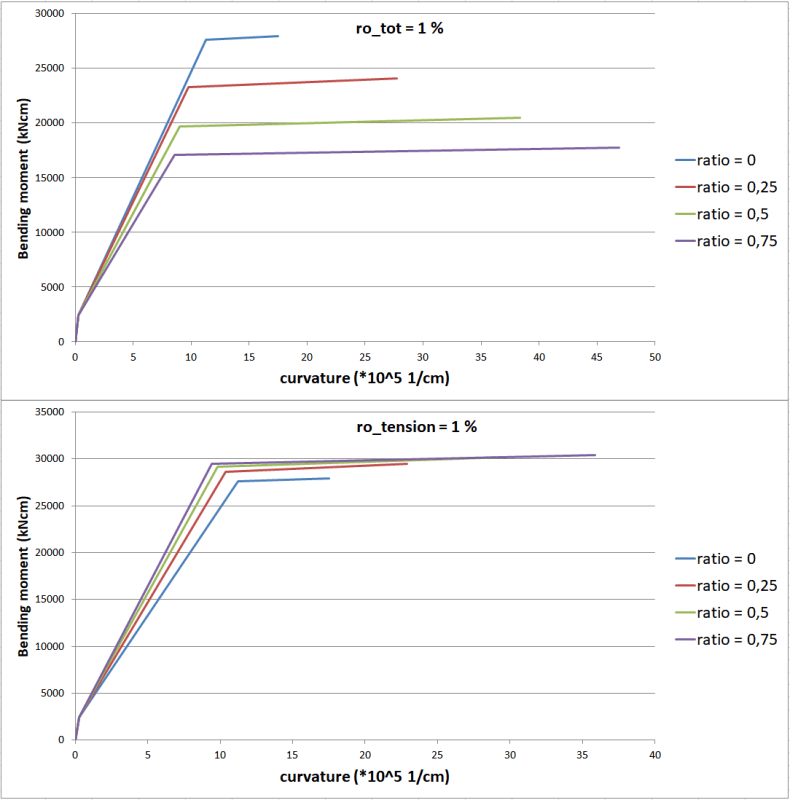
Hello, I did a quick analysis and made two bending moment - curvature diagrams shown in the picture. "Ratio" means the ratio of tension and compression reinforcement (0 means no compression reinforcement, 0,25 means that As in compression is 1/4 of As in tension and so on).
The analysis was done for a 50/30 cm section, reinforcement is in one row (one on top one on the bottom, both 5 cm away from their edge). yield of steel 434,8 MPa, compressive strength of concrete 16,7 MPa, max. strain of concrete 0,35% (bilinear diagram, horizontal from 0,175%), max. steel strain 2%, yield at 0,25%. In short, this is as per eurocode 2 so not exactly the same, but the principle is the same.
moment_-_curvature_diagram_we422c.png


The first diagram shows the case where the total reinforcement is kept at 1% (that's the area of 15 cm^2, so for example ratio = 0,5 means that 10 cm^2 is in tension and 5 cm^2 in compression).
The second diagram shows the case where the tension reinforcement is kept at 1% (that's the area of 15 cm^2, so for example ratio = 0,5 means that 15 cm^2 is in tension and 7,5 cm^2 in compression).

You can see from both diagrams that compression reinforcement increases primarily ductility, not the ultimate moment.
For example, the b. moment values on the second diagram are 100% (blue, ductility 1,56), 106% (red, ductility 2,2), 108% (green, ductility 2,99) and 109% (purple, ductility 3,8).

In short, you won't get any significant improvement in ultimate capacity if you consider compression steel.

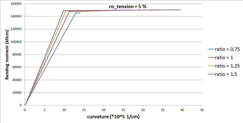
I also did the same thing for 5% reinforcement which is obviously a value that requires compression reinforcement (only the ratio less than 0,75 seemed to crush before yielding so I started at 0,75). Here, the blue line is at 100%, others are at 103% of the bending moment value. Ductilities 1,09 2,36 3,27 and 4,03 respectively.
5_percent_moment_-_curvature_diagram_glyphk.png
 
The discussion was about the effect of the "compression steel", and/or the side face bars, being in tension. In this case not all the tension steel will be yielded.

Doug Jenkins
Interactive Design Services
 
retired13 said:
But, at ultimate state, the total tension steel are yield.
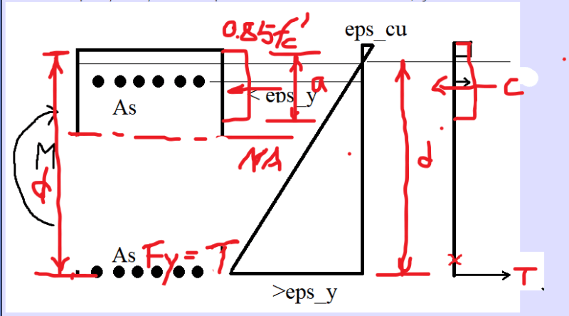
Not necessarily. If you have tension steel close to the neutral axis, it has not yielded. The point that Angent666 was trying to say (I think) is that if steel close to compression side is in tension it probably has not yielded. I drew a picture. The red cross would be the centre of force, right?
steel_mi8cza.png


It makes no sense to me that any steel would reduce shear strength, since three mechanisms are: dowel action (more steel obviously positive), compressed part of the section via friction (this might be reduced, I'm not sure) and third is mechanical interlock (more steel of any kind should help because it would reduce crack width (maybe not significantly, but def. positive) and enhance this mechanism). It doesn't seem probable, at all. Maybe with some weird geometry.
 
I guess we were taught in different ways. Anyway, the sketch below covers what I was talking about.

c_ptifxb.png
 
Status
Not open for further replies.

Part and Inventory Search

Sponsor