Continue to Site

Eng-Tips is the largest engineering community on the Internet

Intelligent Work Forums for Engineering Professionals

  • Congratulations SSS148 on being selected by the Eng-Tips community for having the most helpful posts in the forums last week. Way to Go!

Designing a beam as doubly reinforced though it could be done Single reinforced 18

Status
Not open for further replies.

NewbieInSE

Structural
Dec 19, 2019
234
Hello Engineers,
I'll elaborate it. Say i have a concrete beam having some dimensions, its moment capacity for singly reinforced criteria is 400 kips-ft, say. Moment induced from loads in that beam at the certain location is say 330 kips-ft. It means i can design it as singly reinforced, and say reinforcement requirement is 2.5 in^2 as singly reinforced section.

My question is can i design that section of 330 kip-ft moment requirement, as a doubly reinforced section requiring bottom reinf. say 2.3 in^2, and at top say from calculation .6 in^2 or anything. I think it is possible, considering bottom reinforcement is yielding, but want to know in depth.

I'm actually asking it for existing structural members, which contain less reinforcement (bottom) than required when considered singly reinforced, but contain some top reinforcement which maybe could help in forming doubly action.
Thanks.
 
Replies continue below

Recommended for you

The sketch is wrong.

The strain indicates the neutral axis is above the top steel, but you have added another neutral axis below it.

Doug Jenkins
Interactive Design Services
 
Regarding design for shear, and considering the case where side face reinforcement is included in the bending capacity calculation. Since reinforcement of the side faces will certainly increase the shear capacity, rather than reducing it, I see no problem with designing for shear based on the bottom reinforcement only, whether the side face steel has been included in the bending capacity calculation or not.

The same argument would apply when the "compression" steel is in tension.

Doug Jenkins
Interactive Design Services
 
@retired13
I understand, but my sketch is supposed to explain what IDS and Agent were saying. I'm certain that we'd all agree if we could understand each other. :)
 
IDS,

I see your point now. I misunderstood the problem in concern. However, IMO, the NA above the top steel is no merit in real world design. How much is concrete cover? 2", 3"? The stress above the steel will just break the bond and chip the concrete out. Also, I am not positive about the strain diagram, theoretically the concrete is cracked up to near the neutral axis, I don't know, at this moment, how to draw a representative stress-strain diagram. There is no compression steel in the diagram shown, all tension steel at the bottom face will be yield. the stress in the steel on top face is close, or equal, to zero, because the closeness of the neutral axis. Other side face bars will have stress, relative to the bend shape, in proportion to the tension steel. I wouldn't trust any shear resistance, because the anticipated cracks could have weakened the section too much, thus unreliable (This statement in red is valid for the negative moment region, or for concentrate load coincident with the maximum positive moment).
 
retired13 said:

No, I think others have expressed why in subsequent posts.

hardbutmild said:
The point that Agent666 was trying to say (I think) is that if steel close to compression side is in tension it probably has not yielded. I drew a picture. The red cross would be the centre of force, right?

Correct, that is basically the point I was trying to convey expressed in picture form. Probably not yielded in tension in this case to clarify.

One example of where I've come across the compression face steel ultimately being in tension in practice is when using precast shell beams, in the case of negative flexure the bottom layer of bars in your beam cage on the compression face might have 120-150mm of cover and the compression block depth might only be 100mm deep for example. Another case is when analysing beams with flanges on the compression face, this wider compression block will obviously be sshallower, increasing the chances of the compression face bars being in tension.

Also correctly accounting for the strength contribution from compression face bars in tension is especially important when looking at the overstrength capacity and capacity design requirements in seismic design. If you don't accurately account for the upper bound flexural strength of the beams, then there is a possibility of under cooking the design of the columns and not achieving sufficient margin on the flexural strengths to ensue they are in fact capacity design protected.
 
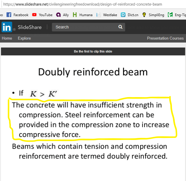
Below is the reason I've doubt on the value of this type of design. Something needs to be done if neutral axis is at, or above the top face steel, as it defeats the purpose to have compression steel, and creates uncertainties.

b_dayt7q.png
 
We are not talking about if the concrete has insufficient strength here. That is the condition whereby a singularly reinforced beam won't satisfy the code is if the balanced strain conditions are not satisfied. This triggers the use of compression reinforcement to reduce the neutral axis depth to below the balanced strain condition. If you are unable to put compression reinforcement within the balanced strain neutral axis depth, well then its hardly compression reinforcement is it! (noting this might be depending on ultimate limiting strain of the concrete and yield strain of reinforcement somewhere in the region of 0.3-0.5 times the member depth, so is unlikely to be above the reinforcement put at the extreme compression fibre in practical terms)

If the reinforcement being added to get to the doubly reinforced condition isn't carrying compression, then you still fail the balanced strain condition. I'd note here, you still need to satisfy the balanced strain condition even if you add compression reinforcement. The act of adding some reinforcement in compression is not enough here, you still need to check the neutral axis depth satisfies your relevant code provisions.

retired13 said:
Something needs to be done if neutral axis is at, or above the top face steel, as it defeats the purpose to have compression steel, and creates uncertainties.

No something doesn't necessarily need to be done, unless of course you are failing the balanced strain conditions. Lightly reinforced beams will rarely have the compression block depth deeper than any top reinforcement. This is irrespective of whether this top reinforcement was considered in the strength calculations or not. From a balanced strian perspective if this check works with a singularly reinforced check, then its clearly going to work with consideration of any reinforcement in compression.

There are several reasons you need compression reinforcement in terms of code provisions typically (ignoring detailing requirements, i.e. having something to have shear reinforcement go round)
1. balanced strain conditions fail for singularly reinforced beam
2. for ductility

 
Retired13 said:
Below is the reason I've doubt on the value of this type of design. Something needs to be done if neutral axis is at, or above the top face steel, as it defeats the purpose to have compression steel, and creates uncertainties.
We are not discussing the case where the "compression steel" is needed to contribute towards the compressive force in the section. The question is if the top face steel being in tension reduces the shear capacity of the section. The answer is, no it doesn't.

Doug Jenkins
Interactive Design Services
 
Gentlemen,

First of all, the linked paper refers Euro Code, so it is an opinion from source other than ACI.

Secondly, IMO, the neutral axis shall not be allowed to be above, even near, the compression steel, since the concrete is not confined, the nominal compressive stress can not be sustained/achieved. Although the so called code requirement on balanced strain condition is satisfied, failure is a sure thing, so something definitely needs to be done to meet the demand - further increase compression capacity and maintain moment capacity, preferably increase beam depth.

Lastly, under such situation with concentrate load coincident with the design moment, the shear strength contributed by the concrete is highly in doubt. There is no such thing "compression steel in tension", it is either compression steel, or tension steel, one way or the other.
 
I am also curios that will that beam satisfies deflection/service criteria, with cracked section properties, not to mention long term effect.
 
hardbutmild said:
Hello, I did a quick analysis and made two bending moment - curvature diagrams shown in the picture. "Ratio" means the ratio of tension and compression reinforcement (0 means no compression reinforcement, 0,25 means that As in compression is 1/4 of As in tension and so on).
Thanks, it has been very beautiful and a time consuming thing u did. It was pretty helpful, i really appreciate it.

JAE said:
Don’t forget that any reinforcement you count on for compression needs to have special consideration for confinement using enclosed stirrups
Yeah, Thanks.
 
NewbieInSE,
The title of this thread is about DESIGNING a beam using reinforcement near the top to assist with bending when the top is in compression. My answer to that is that it is is foolhardy to do so, as the reinforcement needs to be near the tension face.

Then, reading the thread, you reveal this is an existing beam which you are trying to ANALYZE in hopes of tweaking the beam's capacity. You are new, but you need to understand the difference between analysis and design.

An important distinction needs to be made between the comments of especially retired13 and IDS. retired13 talked about Whitney stress block and plastic design. That is a design method, but your section must remain plane in practice, as IDS has explained. Therefore, steel near the top will not be stressed to a level which will help much.

 
Thanks hokie66
hokie66 said:
Then, reading the thread, you reveal this is an existing beam which you are trying to ANALYZE in hopes of tweaking the beam's capacity. You are new, but you need to understand the difference between analysis and design.
I understand the difference between Analysis and Design. You are right about my intention to tweak the beam's flexural capacity a little bit, as the beam is already existing. In case of new design, i wouldn't do that. Actually, in case of Retrofit projects I thought it would save some beams coming under Retrofit requirement if 'Program's calculated reinforcement considering the beam as singly reinforced' could be a little reduced taking the advantage of top provided (in drawing) compression reinforcement considering doubly reinforced beam analysis.

And in regards to the followed discussion regarding 'reduction of shear capacity related to beam d', i will have to read it well, i did not understand fully but partially.
 
The idea that adding top steel, or any steel above the bottom, will reduce the shear capacity is illogical and relies on a misinterpretation of the code provisions for shear.
 
retired13 said:
I am also curios that will that beam satisfies deflection/service criteria, with cracked section properties, not to mention long term effect.
Agent666 said:
Also correctly accounting for the strength contribution from compression face bars in tension is especially important when looking at the overstrength capacity and capacity design requirements in seismic design.

These are two very interesting topics, but I think we'll go way offtopic if we start discussing them, we need a thread about everything and anything.
 
IDS said:
it would be very unusual for the steel closest to the compression face to be yielded in tension.
Retired13 said:
However, IMO, the NA above the top steel is no merit in real world design.
Agent said:
Lightly reinforced beams will rarely have the compression block depth deeper than any top reinforcement.
To add another (admittedly "unusual") perspective here, my beams very often have "compression face" reinforcement that either reaches 50% or even full tensile yield, particularly for positive flexure in T-beams. I expect this is precisely due to Agent's caveat -- I tend to have very lightly reinforced beams with small bar sizes due to local economics. While these bars don't add a lot to the flexural capacity, because I tend to have a lot of bars in the top face, it often is noticeable. Not the efficient choice to address moment in one particular direction, but can save some steel overall when considered.

For the topic of deflections, I do find that my sections tend to crack more than the typical 70-35-25% ACI factors, and design accordingly. A lot of my beams come out with effective modulus of inertia closer to 25% Ig.

Retired13 said:
I wouldn't trust any shear resistance, because the anticipated cracks could have weakened the section too much, thus unreliable
I don't think this statement is based in real behavior (although as a conservative measure, you're welcome to trust or distrust at your leisure). I've not seen research or codes indicating that flexural cracking would impact concrete shear capacity. It's usually not even visible.

As to Celt's discussion of the depth d used for shear capacity -- I would bet a nice meal that was a case of poor wording intending to consider cases of a beam with multiple layers of steel close to the tension face of the beam -- not for skin reinforcing, or for other steel relatively far from the tension face.

----
just call me Lo.
 
To add another (admittedly "unusual") perspective here, my beams very often have "compression face" reinforcement that either reaches 50% or even full yield, particularly for positive flexure in T-beams.

Yield in Compression, or yield in tension?
 
Considering compression reinforcement generally only increases capacity by no more than 5% - this is why so many engineers neglected it, well, at least engineers that don’t need a computer for everything.
 
Lo said:
I've not seen research or codes indicating that flexural cracking would impact concrete shear capacity. It's usually not even visible.

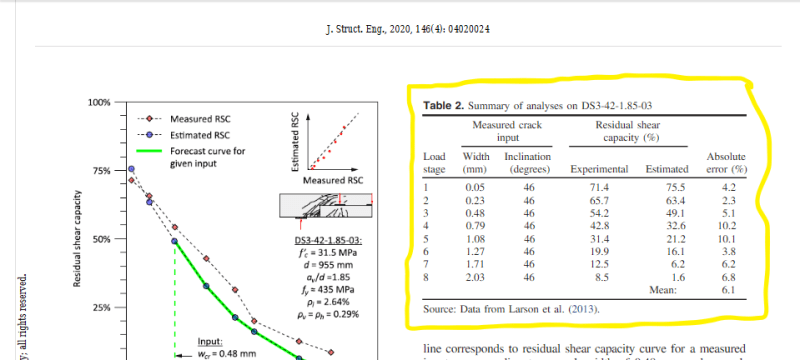
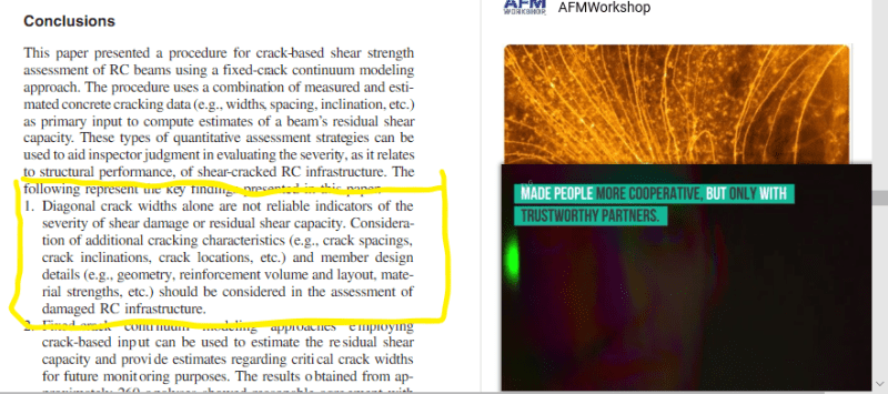
Neither do I. The most close study I can find is a paper published on ASCE Structural Engineering Journal, Link, dated January 2020.

Note in the world of "shear", everything is uncertain and inconclusive. Conservatism and prudent in design shall prevail.
Below are excerpts from the article.

a_yxkdd0.png


a1_vmpgid.png
 
Status
Not open for further replies.

Part and Inventory Search

Sponsor