Eng-Tips is the largest engineering community on the Internet

Intelligent Work Forums for Engineering Professionals

Designing an atmospheric storage tank recirculation system - pump control strategies? 2

Status
Not open for further replies.

HaxNobody

Chemical
Aug 6, 2024
19
0
0
US
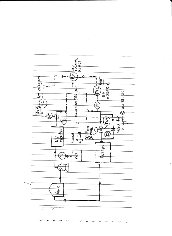
I'm working on a 10,000 gallon storage tank for reverse osmosis purified water that needs to be recirculated through a UV sanitizing reactor. I would like help on the correct strategy for controlling the pumps in this loop. The loop design is as follows:

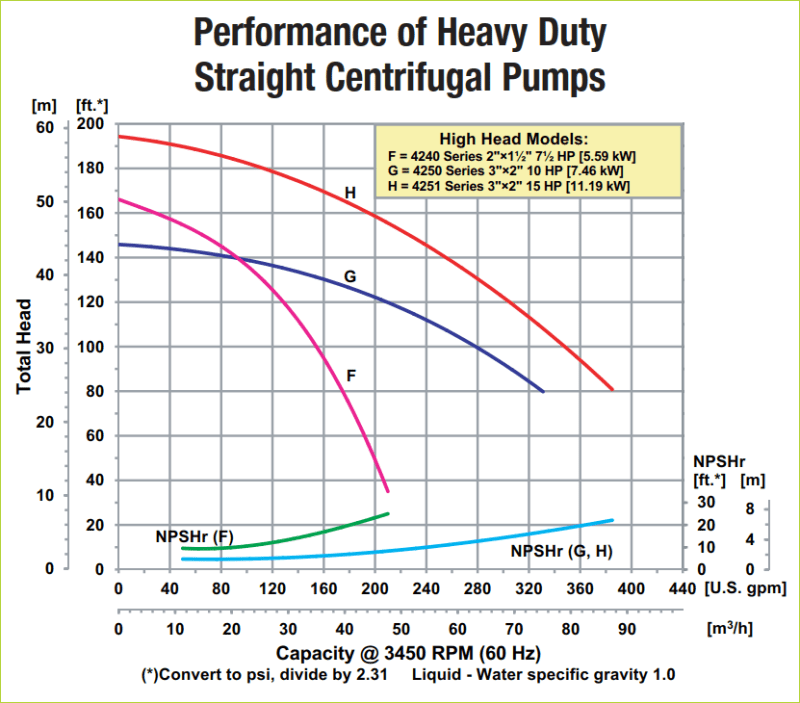
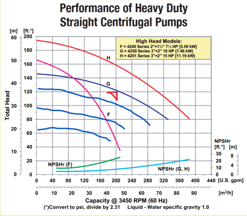
I have two 10HP centrifugal pumps in parallel, each with its own check valve on the discharge. They can achieve up to 62 PSI of head pressure at zero flow. These pumps feed directly to the UV reactor.
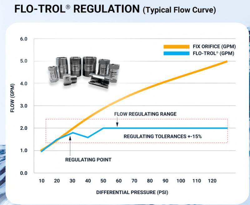
After the UV reactor, I have a 240 GPM flow restrictor valve that is intended to prevent the UV system from exceeding its design flow rate. This restrictor valve could have 15-20 PSI drop when running at its full flow rate.
The line then goes out to the process loop, where various equipment taps in to draw from the loop to feed mix tanks and other processes. The loop pressure should be around 30 PSI when recirculating under "idle" conditions with no draw off the loop.
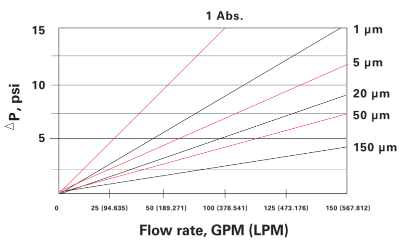
When the loop returns, it goes to a set of 1 micron absolute rated sediment filters.
After the filters, the loop then goes to a backpressure regulating valve that is set to maintain around 170 GPM of tank return flow when the loop is idle, to achieve 1 tank turnover per hour.
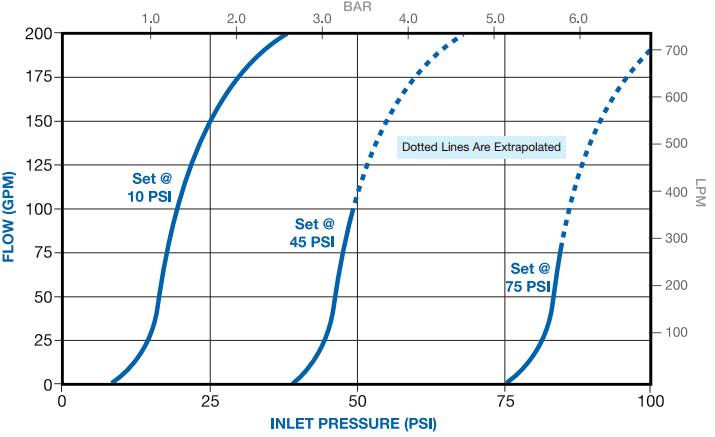
The backpressure regulating valve is set to 10 PSI, and it will maintain around 30 PSI at design flow. If the loop pressure drops because other processes are drawing from it, the backpressure valve will close and create a "dead leg" at the end - to prevent this, the backpressure valve also has a 10 GPM flow restrictor in parallel to ensure some amount of minimum flow is still achieved.

Both pumps are on their own VFDs, and I originally intended to control their speed based on a pressure sensor located just before the backpressure regulating valve at the end of the loop. However, I have identified a problem: If the loop pressure is too low because it is being drawn down by process equipment, this strategy would cause the pumps to keep running faster and faster, even though the 240 GPM flow restrictor is going to prevent them from performing additional work. So I need to figure out how to "reset" the pump speed based on flow across the UV reactor. I'm not sure whether I should try and detect actual flow, or if I should try and put a pressure sensor on the UV reactor and try to calculate the differential to estimate flow rate.

There may be other pitfalls that I have not yet identified that you guys might know about. Looking forward to any insights on this - thanks!
 
Replies continue below

Recommended for you

The pump curves and a sketch would be helpful. My first thought is to control pump speed with lead lag configuration and flow meter for the 170 gpm minimum flow setpoint. Any usage upstream will be seen and the pumps can adjust accordingly. Are there any actual pressure requirements for the process equipment in the loop? If not, then the pressure can vary, and you are only concerned with flow at that point.
 
Some basic clarifications first:
a)If the backpressure control valve is set to maintain a backpressure of 30psig, then why do you say "The backpressure regulating valve is set to 10 PSI,.."?
b)There is also the variable pressure drop across the filters as they gradually fill up with sediment. So shouldnt the backpressure PCV be upstream of the filters ?
c)How are the filters switched over from one to the other, manually or on auto sequence depending on a max permissible dp ?
 
Heaviside1925 said:
The pump curves and a sketch would be helpful. My first thought is to control pump speed with lead lag configuration and flow meter for the 170 gpm minimum flow setpoint. Any usage upstream will be seen and the pumps can adjust accordingly. Are there any actual pressure requirements for the process equipment in the loop? If not, then the pressure can vary, and you are only concerned with flow at that point.

I will try to get a sketch drawn up. I do have a minimum pressure requirement for one piece of the process equipment, but I can coordinate that with the tank fill operations so that I don't go too low.
Pump curve is line "G" here:
pump_curve_xgsfum.png


georgeverghese said:
Some basic clarifications first:
a)If the backpressure control valve is set to maintain a backpressure of 30psig, then why do you say "The backpressure regulating valve is set to 10 PSI,.."?

I am estimating this based on the curve that the valve has, since it is not linear. The specific valve is a Plast-O-Matic RVTX device, and the curve is here:

rvtxperformance_wqfwlh.gif


georgeverghese said:
b)There is also the variable pressure drop across the filters as they gradually fill up with sediment. So shouldnt the backpressure PCV be upstream of the filters ?

That is a good point that I did not consider. That will change my piping layout for sure.

georgeverghese said:
c)How are the filters switched over from one to the other, manually or on auto sequence depending on a max permissible dp ?

I have 4 filters in parallel that are rated for a maximum of 50 GPM each. I would shut them off one-by-one with their own isolation valves during changeouts. We have not had an issue with filters loading up in a similar install elsewhere, but have generally just changed them out yearly "just because" as far as I can tell. Here is the filter curve for the 1 Abs. filters - they are rated for 40 PSI delta-p maximum:

filter_curve_ylphxm.png
 
You can set this up without complicated controls and VFD's.

– Continuously flowing in a temperature and pressure controlled loop.
– Supply and return piping with a back pressure control station at the end of supply.
– Loop flow can be determined using 1.8 x average total consumption.
– Used to accommodate peak demand and maintain proper velocities.

 
 https://files.engineering.com/getfile.aspx?folder=7559058a-1717-4b02-b081-7fa45176e94e&file=16T_-_Ultrapure_Water_for_SRF_Applications.pdf
I have two 10HP centrifugal pumps in parallel, each with its own check valve on the discharge.
So the two pumps are for redundancy, not running in parallel? Based on the curve, only one is needed in service if 240gpm is the max flow rate of the system.

the backpressure valve also has a 10 GPM flow restrictor in parallel to ensure some amount of minimum flow is still achieved.
Why is this needed?

If the loop pressure is too low because it is being drawn down by process equipment, this strategy would cause the pumps to keep running faster and faster, even though the 240 GPM flow restrictor is going to prevent them from performing additional work.
Why is this a concern?

And to echo bimr Why is there a need for VFD control?
 
Heaviside1925 said:
So the two pumps are for redundancy, not running in parallel? Based on the curve, only one is needed in service if 240gpm is the max flow rate of the system.

Correct, I want to have a "hot spare" and will probably alternate them every week or so. However, my flow restrictor setup is actually a pair of Flomatic CDK120 valves in parallel, and these might not pass the full 240 GPM until the delta across them is extremely high, according to a curve I found for them. Something like 30 PSI. So I might need the second pump to achieve the loop pressure I'm targeting under full flow conditions. Unfortunately, I can't find the exact curve for my valves, only their "typical curve":

restrictor_curve_le6fdi.png


Heaviside1925 said:
Why is this needed?

Because when I am filling multiple mix tanks at the same time, the loop pressure could drop below the backpressure valve setpoint and cause the flow to be shut off completely, creating a dead leg.

Heaviside1925 said:
Why is this a concern?

And to echo bimr Why is there a need for VFD control?

If I can achieve my target flow with a pump running at less than full speed, then I don't see any good reason to run it at full speed. Most of the time, the loop will be "idle", running at 170 GPM and not needing the full pump flow rate. From my interpolation of the pump curve, I think I should be able to run one pump at 60-70% speed and achieve both the pressure and flow rate that I need for the idle loop condition, and I can then set a higher PSI target when I am filling a tank from the loop.
 
So what is wrong with creating a dead leg if the backpressure valve were to full close ? You've got high consumption at users, high flow through the UV reactor, so the pump is not dead headed. The filters wont have any flow, but that isnt a problem.

"Because when I am filling multiple mix tanks at the same time, the loop pressure could drop below the backpressure valve setpoint and cause the flow to be shut off completely, creating a dead leg."

Think you've got a cheap self operated backpressure valve at the moment, which doesnt maintain backpressure at 30psig at all flows, if I interpret the 10psi line correctly - at flows less than 170gpm, upstream pressure is lower, so it really isnt doing much "regulation". Here is what I think is a better self operated valve for constant backpressure no matter what flow the valve passes; a pilot operated backpressure regulator :

 
haxnobody

I can't make any sense of this at the moment so bear with my questions and comments. At the moment it looks like you're doing Apollo 13 engineering here - just throwing together anything you can find and then seeing what happens?

So to start with the design basis - always a good place to begin.

What do you want this system to do?
Looks to me like you have two modes of operation
1) Providing RO water which has gone through a UV filer (though not strangely a 1 micron filter?) to various consumers at a max supply pressure of ?30 psi?
Your max flow through the UV filter is 240 GPM, but you don't state a minimum supply pressure or a max demand from the users??
2) recirculating water at 170 gpm (why not 240?) going through the UV filter and a 1 micron filter back into he tank in order to recircualte a 10,000 gal tank in one hour ( is one hour critical? a bit more or a bit less would be ok as well?

The way you're planning to do it has some issues for me.

1) Using a VFD is not valid here. The flow rate difference is small, VFDs cost money and also use about 8 to 10% of the motor power and eject it as heat, so then you need to ventilate or cool the romm the VFDs are in. When you control flow on a centrifugal pump using a valve the power consumed goes down so the power savings are not always what you think.

2) Why are you not filtering straight after the UV equipment?

2A - The flowmatic valves control on constant flow and hence the DP across them is merely a function of the pressure available , but you are correct, they need about 30 psi to get close to their rated flow, at which point flow stays the same, but the DP goes up. They are simple and small, but you could easily replace them with a proper control valve which could have a much lower DP when fully open if that flow was under 240 gpm. The 120gpm is the biggest one, but why are you fixed on using these? They are good for some services, but not for your use.

3) That back pressure valve you're using is nothing of the kind. It's a pressure relief valve set at 10 psi and your 30 psi / 170 gpm is the max it will flow through so I don't think it will last long and your flow is not being controlled to 170. Think about what you need here. Is it a back pressure of 30 psi and then when it goes lower the valve closes or do you want 170 gpm regardless? If you just want 30 pis and whatever flow is spare then use a proper back pressure control valve, not a relief valve that you're squirting water through at a far higher flow than it is designed for.

4) what's the issue about a dead leg for a little while? You can take a small bleed off the header if you want, but for water it's pretty rare to do this unless its going to be a dead leg for a long time.

5) You are using umps which seem to be too powerful and hence will use a lot of power if you're running this thing 24/7? If you design this right, your required head could be 40 psi @ 240 gpm, not 65..

So maybe TLDR, but just use the pumps as fixed speed and use proper control valves. That one you have on the outlet of the pump will control on flow and pressure drop could be very small or quite big depending on what your demands are. There are much better ways of doing this than your current design. IMHO.


Remember - More details = better answers
Also: If you get a response it's polite to respond to it.
 
What I'm finding out is that I should have posted a lot earlier into the process to get help rather than waiting until now. In any case, the good thing is that some changes can still be made based on input from you all. I'm approaching this from a small amount of practical experience and no formal training, so I appreciate all the input. My expertise is in the electrical side of things, which is why I prefer variable controls: because I know how to make them bulletproof. This is my second time designing a piping system of this nature, and this one is 4x the capacity of what I have worked on before. With that said, I'll try and keep up with the incoming responses to the best of my ability.

First, I missed this post:

bimr said:
You can set this up without complicated controls and VFD's.

– Continuously flowing in a temperature and pressure controlled loop.
– Supply and return piping with a back pressure control station at the end of supply.

Got this. Sounds like the valve I chose for backpressure control doesn't live up to members' expectations, although it is rated for this purpose, with continuous flows up to 200 GPM.

bimr said:
– Loop flow can be determined using 1.8 x average total consumption.
– Used to accommodate peak demand and maintain proper velocities.

I'm not sure where I would be measuring consumption here for the purposes of the flow calculation you posted.

OK so now:

georgeverghese said:
So what is wrong with creating a dead leg if the backpressure valve were to full close ? You've got high consumption at users, high flow through the UV reactor, so the pump is not dead headed. The filters wont have any flow, but that isnt a problem.

My thought on this is as follows: Since this water is not treated with any biocides, and the UV only works as far as the light can reach, any stagnant area could allow bio growth from whatever might have escaped the UV and made it into the loop. Maybe this should not be a concern, but I don't have enough experience with this part of the design.

georgeverghese said:
Think you've got a cheap self operated backpressure valve at the moment, which doesnt maintain backpressure at 30psig at all flows, if I interpret the 10psi line correctly - at flows less than 170gpm, upstream pressure is lower, so it really isnt doing much "regulation". Here is what I think is a better self operated valve for constant backpressure no matter what flow the valve passes; a pilot operated backpressure regulator :

I had attempted to quote a pilot operated valve, but the manufacturer I had talked to was unable to guarantee that the materials of construction would not leech into the line. Although I'm NOT running 15-18 megohm UP water in this loop, the 5-7 megohm conductivity of my R.O. outlet does still have the potential to corrode copper and iron, so I have to be careful about that. I'll look into your Emerson suggestion further.

LittleInch said:
What do you want this system to do?

I'll try to explain:
1. Idle flow. The "1 tank turnover per hour" is nothing more than a magic number that was given to me by the folks that provided the R.O. system. I don't know how valid it is or what it is based on.
1a. The UV reactor was specified at an industry standard dose of 30 mj/cm2, and any flow rate less than design will increase that dose rate, which is only ever a good thing. Obviously having the flow rate go too low will cause it to overheat, but we are nowhere close to the minimum flow in any situation here.
2. There is only one piece of process equipment that has a pressure and flow requirement. The requirement is between 26-52 PSI and 49 GPM, so I targeted 30 PSI and 50 GPM in my estimations. This equipment is a venturi inductor for bringing premix chemicals into the main water mix tanks.
3. Tank filling. I have 2 inch valves tapped off of my 3 inch recirc header for bulk-filling of up to 8 separate mix tanks. I can limit the number of tanks filling at a given moment if necessary. I guesstimated 100 GPM would flow when performing bulk tank fills, and that I could fill up to 2 tanks simultaneously at around 200 GPM.

LittleInch said:
1) Using a VFD is not valid here. The flow rate difference is small, VFDs cost money and also use about 8 to 10% of the motor power and eject it as heat, so then you need to ventilate or cool the romm the VFDs are in. When you control flow on a centrifugal pump using a valve the power consumed goes down so the power savings are not always what you think.

I like drives for a number of reasons beyond potential energy savings: From a single device, I get overload protection, soft start capability, seal failure detection, ground fault protection, and run-dry protection to mention just a few things. Many of these things would require separate discrete parts and pieces to implement with bang-bang controls.

LittleInch said:
2) Why are you not filtering straight after the UV equipment?

The bio load after the UV reactor should be at its lowest at that point. Anything thereafter (piping, equipment, valves, etc) is a location that is not exposed to UV and is a potential area for growth, so my thought was that I would protect my tank by having the filters at the end of the loop. I have also considered an in-tank UV system which would basically mean that the filters aren't contributing much, but the in-tank UV is pretty expensive and may not be an option.

LittleInch said:
2A - The flowmatic valves control on constant flow and hence the DP across them is merely a function of the pressure available , but you are correct, they need about 30 psi to get close to their rated flow, at which point flow stays the same, but the DP goes up. They are simple and small, but you could easily replace them with a proper control valve which could have a much lower DP when fully open if that flow was under 240 gpm. The 120gpm is the biggest one, but why are you fixed on using these? They are good for some services, but not for your use.

I could use some help specifying better valves for this purpose. I had been talking to Flomatic but their pilot operated valves are only available with epoxy coated cast iron and they couldn't guarantee that the wetted surface would always be compatible with my water to prevent degradation over time. So they offered the passive valves as an alternative.

LittleInch said:
3) That back pressure valve you're using is nothing of the kind. It's a pressure relief valve set at 10 psi and your 30 psi / 170 gpm is the max it will flow through so I don't think it will last long and your flow is not being controlled to 170. Think about what you need here. Is it a back pressure of 30 psi and then when it goes lower the valve closes or do you want 170 gpm regardless? If you just want 30 pis and whatever flow is spare then use a proper back pressure control valve, not a relief valve that you're squirting water through at a far higher flow than it is designed for.

The manufacturer claims that it is rated for continuous flow up to 200 GPM, but I do understand where you are coming from and an alternative would be good to look into. I'm not completely cost-constrained, but $5k for a valve like this isn't something I can approve on my own and will cause some pushback.

LittleInch said:
4) what's the issue about a dead leg for a little while? You can take a small bleed off the header if you want, but for water it's pretty rare to do this unless its going to be a dead leg for a long time.

I may be overthinking that part of it, but it was a minimal cost adder and seemed to make sense. Indeed, it shouldn't happen often or for very long.
 
Ah, that makes a difference.

So if most cheap metals are no good, you're probably better off with PP body butterfly valves with electric actuators for your control system.

Example here
I can see you're wedded to VFD.s but really don't need to use it as such even so. Just ramp it up to 50 or 60 htz then bypass the VFD.

Your flow controller can be set at 240 gpm d/s the pump using a simple control loop but you would need to measure flow somehow. Cheapest is orifice plates, but you could use ultrasonic, turbine or a variety of other.

Then set your other control valve / butterfly valve to control at say 35psi u/s the filter but you can set a min closure so you would always get soome flow into the tank. Then as you users use the flow and the pressure falls the d/s valve closes and all flow minus yur dribble into the tank goes to the users, but maxed out at 240 from the U/s valve.

This means you are flowing at 240 all the time, but that's not a lot more than 170. Or set a high pressure at say 45 psi and control on VFD speed if you really want to use one of them. Or set this as an extra input into the control valve d/s the pump to reduce flow.

Those current valves you have are just not good for what you're trying to do, especially that d/s one. As soon as other users flow, the pressure will fall, but the so called back pressure valve won't stay at 30 psi because there isn't enough flow to go through it to generate the DP until you get to 10 psi when it stops flowing.

You might be able to get away with a slightly lower head / lower power pump as well once you arrange things correctly.


Remember - More details = better answers
Also: If you get a response it's polite to respond to it.
 
I'm looking at a Flomec TM30SQ9GMD turbine meter with a 4-20ma output module for flow measurement, although they do have an ultrasonic alternative. I like the idea of either passive or pilot operated valves so there's no logic or programming involved to go wrong.

Unfortunately the pumps are the one thing that I cannot change at this point.
 
OP,
Based on the pump curve you provided, I am guessing you did not actually have a vendor size your pumps. You may not need new pumps and an impeller swap may get you where you need to be if changes are required. Since you are using a VFD for speed control, I would expect to see a pump curve such as below, show the effects of rpm/flow and pressure. You should consider efficiency as well. Most pump vendors should be able to provide a much more application specific sizing. (Sry for the sloppy edit but I think it conveys the point)
vd14x6gu_pesbfa.png

I suspect you have enough pipe losses to keep your pump from exceeding 240gpm and even if you don't, you can set a max rpm to keep the pump from exceeding the max flow. If you have a process user that can run the pump past the required flow rate, consider restricting the flow of that user. Have you done the actually hydraulic calcs to determine your pipe losses? If not, start there.

I think you can achieve a well-functioning system without a VFD but as previously noted, you seem married to a VFD and if so, I would use a restriction orifice sized for choked flow at 170gpm using your system pressure @170gpm (head-pipe and elevation losses) with a flow meter for your tank return.Edit-this is incorrect. For a flow meter on this line, lots of options, DP, turbine, I would even consider a vortex for this application. PID loop, SP 170gpm for the VFD speed within a min-max rpms range based on the pump curve. Do the hydraulics to confirm but I think this would be the simplest and still have VFD control.

I am still not convinced about your dead leg concern. If you do have a user or users exceeding 240 gpm total, then those individual users should be addressed and either adjust the use sequence and/or restrict to these users. I don't think it's a very advisable design to only have 240gpm available for users exceeding 240pgm.
 
Most of the passive or pilot operated control valves use a diaphragm to move a needle or a disc and they tend to be metal valves. The PP bodied butterfly valves are quarter turn and need a pneumatic or electric actuator. The logic is very simple really and with that fluid the pilot type valves might not last ss long as the m they would normally.

I can't see an orifice working. When you want flow to your users you want virtually no flow returning to the tank. You can only do that with a control valve.

Remember - More details = better answers
Also: If you get a response it's polite to respond to it.
 
HaxNobody (Chemical)(OP) said:
If I can achieve my target flow with a pump running at less than full speed, then I don't see any good reason to run it at full speed. Most of the time, the loop will be "idle", running at 170 GPM and not needing the full pump flow rate. From my interpolation of the pump curve, I think I should be able to run one pump at 60-70% speed and achieve both the pressure and flow rate that I need for the idle loop condition, and I can then set a higher PSI target when I am filling a tank from the loop.
These ultrapure water loops are not necessarily constructed for efficiency. There are issues such as maintaining velocities to sweep the microorganisms off the piping walls.


Heaviside1925 said:
I suspect you have enough pipe losses to keep your pump from exceeding 240gpm and even if you don't, you can set a max rpm to keep the pump from exceeding the max flow. If you have a process user that can run the pump past the required flow rate, consider restricting the flow of that user. Have you done the actually hydraulic calcs to determine your pipe losses? If not, start there.

Hmm. I haven't kept up with my hydraulic calcs since I first started this project. I'm looking at 330ft of 3" sch80 PVC pipe with (8) 90s and (5) tees. That's 57 PSI drop at the tail end of the loop at 170 GPM, although still only 33 PSI drop to the farthest consumer. I'm estimating this based on numbers from this nomograph, 7.9 ft per 90 elbow, and 6.1 ft per tee run. My nearest consumer is only subject to a 15 PSI drop from pipe losses, and it's the one that has the minimum flow and pressure requirements. The remaining consumers are just bulk filling of atmospheric mix tanks.

So the numbers that I ran for the first consumer are still good, if I can avoid using the passive flow limiting device. I would need to either switch to a valve with lower pressure drop, or control actual measured flow with pump speed. The mix tanks at the end of the loop will probably fill much slower than the ones at the beginning, and I will only be able to achieve my minimum tank return flow rate if my filters are brand new. Its looking like I might not even need a backpressure valve at all based on pipe friction losses. I have to think about this some more.
 
If you are doing an ultrapure loop, you might want to review the file posted earlier as PVC pipe is not acceptable.
 
bimr said:
If you are doing an ultrapure loop, you might want to review the file posted earlier as PVC pipe is not acceptable.

Thanks, I did review that document and it was very interesting. This is sort of a "medium pure" setup, no idea if there is an actual technical designation for that. We are trying to maintain the output of the R.O. system directly at 5-7 megohms and not going for a complete ultrapure filtering/polishing all the way up to 18.2 megohms. The main concern is biological growth. I do understand the concern regarding PVC leeching out solvents and dyes, but I'm not sure how to quantify how much of this could occur in practice. I based this off of a couple of previous designs that also used PVC without appearing to introduce any issues in the process.
 
I have edited my previous post based on LittleInche's comments. The suggestion of a passive or active control valve could be more appropriate since it would allow for future flow and pressure requirement adjustments.
 
Think you can do without that 240gpm restrictor which burns a lot of pressure. The scheme I have in mind to load the VFD for the pumps is as follows:
a) Install a flow element and FT downstream of pumps or downstream of UV steriliser. Configure a reverse acting hi set FIC with this - setpoint 240gpm - this will be the override controller to provide the load signal to VFD
b) Retain the current plan to sense pressure just upstream of backpressure regulator and configure a direct acting PIC with this - normal setpoint 25psi - this will load the pump VFD most of the time
c) Configure in your control system an auto signal select to select the FIC output when it reaches SP of 240gpm, thus cutting off the PIC output from going to VFD

See diagram attached. This scheme enables you to operate the pump at the min required supply header without losing developed pressure, so it saves on power. If you dont have PLC, you can just as well configure all this with equivalent pneumatics devices, all mounted locally.

UV_water_supply_controlsA8thAug2024_n1xm1i.jpg
 
Status
Not open for further replies.
Back
Top