Eng-Tips is the largest engineering community on the Internet

Intelligent Work Forums for Engineering Professionals

Detailed thread now showing well on drawing

Status
Not open for further replies.

VW181

Mechanical
Jan 23, 2013
122
0
0
NL
Hi all,

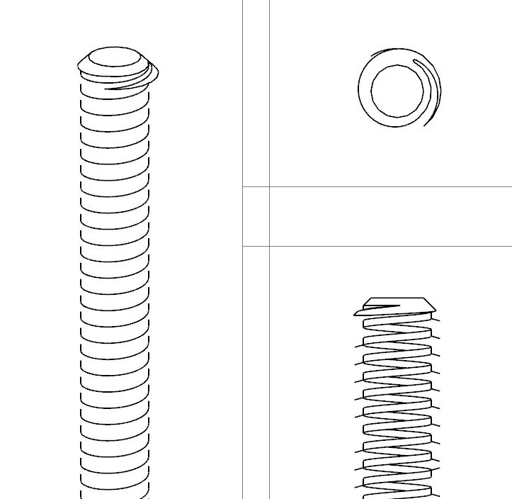
I've made an piece of threaded rod with trapezoid/acme thread. But when I create an drawing of it, it is only showing an part of the thread.
Yesterday in my first attempt it was showing only the two chamfers at the ends and nothing els. So it looks like an graphical problem.
The thread is showing well in the isomeric view in the assembly drawing.
An while ago I created another spindel with some more features on it and that one had no big problems. Only in the isometric view wasn't showing well, until i rotated it a bit and then it showed well.

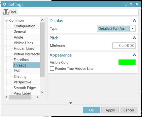
Are there some settings I can change to get an correct view?

Working on NX 10.0.3.5 and Teamcenter 11

Thread_not_showing_well_svww8o.jpg


Using NX 10.0.3.5 and Teamcenter 11.2.2.1 on Windows 10 (64)
 
Replies continue below

Recommended for you

The two chamfers that you see, is that a top view of the thread? If so, the chamfer edges are probably covering your thread curves (same diameter)

Ronald van den Broek
Senior Application Engineer
Winterthur Gas & Diesel Ltd
NX9 / TC10.1.2

Building new PLM environment from Scratch using NX12 / TC11
 
Select the view on the drawing, right click and find a field named "tolerance" or maybe "view tolerance".
zoom in slightly, then set this value to "0" and press apply.
NX will then try evaluate a reasonable value for the tolerance since 0 is impossible.
Most often when I see cases like this , the "0 tolerance" does the trick.
Note that the zoom when pressing apply, has influence .

Regards,
Tomas


Thank you all for the reply's.
The "0" tolerance did the trick.
I already tried manually small till large view tolerances without result, but after "0" I have goed views.

@ mmaulding: created with the "thread" command.

@NutAce: The top-right view is the top view, with indeed an chamfer. Although is't covering the thread, it should still be an full circle at the out-side.
(Ik had jou aan je naam te zien ook in het Nederlands kunnen antwoorden)

Using NX 10.0.3.5 and Teamcenter 11.2.2.1 on Windows 10 (64)
 
Today I'm working on an assembly with this threaded rod in it. Sadly again the same problem with this part in the drawing. And now the "0" tolerance is not working.
Best option now is to set in the "view settings" the "Representation" on "Smart Lightweight". Although still not perfect, it's almost good.

Any other suggestions?

Using NX 10.0.3.5 and Teamcenter 11.2.2.1 on Windows 10 (64)
 
Is there a good reason you have it in "detailed mode" and not symbolic ?
Cutting detailed threads is a safe method of producing slow drawing updates...
If somebody would ask me "Detailed or Symbolic threads ?" my answer is always :
"Detailed ONLY if you intend to use the surfaces for CAM or producing a mold to cast that thread."

that said, the surfaces in a thread are pretty complex and heavy to calculate, and the complexity increases with the length of the thread.

Regards,
Tomas

 
I know it's more complex for NX, but we very rarely use trapezoid/acme thread, so just to be clear it's different than normal I used "detailed mode".

Using NX 10.0.3.5 and Teamcenter 11.2.2.1 on Windows 10 (64)
 
How should I do that Jerry?
But detailed thread on the drawing is just the problem, so what will solve it to do the thread in modeling as symbolic?

Using NX 10.0.3.5 and Teamcenter 11.2.2.1 on Windows 10 (64)
 
Look into the view setting of the drawing view,
Go into the threads setting,
Pick one of the detailed settings.

Even if you modeled it as a symbolic thread, it will show as detailed.

Capture12_iprzo1.jpg


Jerry J.
UGV5-NX1884
 
Status
Not open for further replies.
Back
Top