Continue to Site

Eng-Tips is the largest engineering community on the Internet

Intelligent Work Forums for Engineering Professionals

  • Congratulations KootK on being selected by the Eng-Tips community for having the most helpful posts in the forums last week. Way to Go!

Detailing of required reinforcement with slab offset 2

Status
Not open for further replies.

chritsar

Structural
May 9, 2022
11
Suppose we have a slab with an offset that at the same time acts as a supporting beam (happens a lot in projects where there is an underground garage for example). In the static analysis the slab is assumed to be continuous. The beam acts as a support therefore the moments in the slab will be negative requiring top reinforcement.

The question: Is it enough to anchor the top reinforcement inside the width of the beam? Or is it necessary to overlap the required reinforcement with the beam stirrups in order to provide continuity of the moment resistance between the top and bottom slabs?

By my estimate, this has to do with the width of the beam (b in the sketch). In sufficiently wide beams (how would that be defined though?) the beam can be assumed as fully rigid and therefore I would expect a mere anchorage of the slab reinforcement to suffice. If the beam is not wide enough (perhaps close to the depth of the slabs) then I would expect a need for overlapping the required reinforcement of the slabs with the beam stirrups so the moment can be fully transferred.

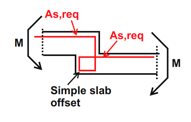
Below I have two sketches: One is the described situation - slab offset as a supporting beam and the second is a typical slab offset with the proposed reinforcement for moment continuity.
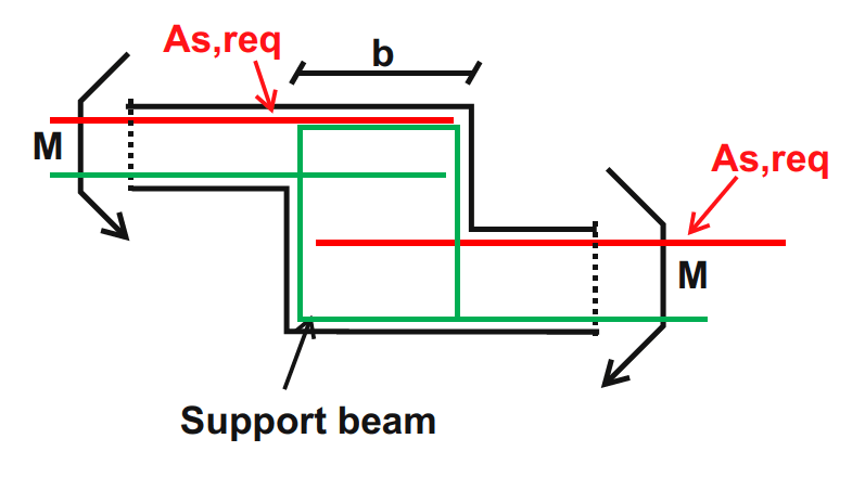
Support_beam_-_offset_tb25zr.png

Simple_slab_offset_dbtclp.png
 
Replies continue below

Recommended for you

dijon said:
note that if this is for a beam seeing shear in-and-out of the page that you should be providing additional stirrups for this moment transfer mechanism in order to not over-utilize the stirrups designed for beam shear

I somewhat disagree. The tension that this would produce on one side would be offset by compression clamping on the other side of the beam. That clamping can be used to resist shear, making the setup "shear neutral" in theory, if a bit eccentric.

dijon said:
...this would be considered a discontinuous "D-Region" that should be analyzed via strut and tie methodology.

In my experience, nobody actually designs slab steps via strut and tie. In fact, the only designer that I've ever seen attempt it is me and I didn't get too far. I feel that it's important to acknowledge this as being the reality of design practice. Strut and tie is conceptually useful for these thing in as much as it facilitates meaningful discussion of the details. That's where it's usefulness ends, however, in my opinion.

dijon said:
My only qualm with Kootk's "Cadillac" version of the detail is that to me the hooked bar at the top may not strictly be anchored to Node 1...

I agree. In my experience, none of the details wind up being fully STM compliant at a number of the nodes, and for a number of reasons. As I mentioned above, however, I've made no attempt to make the details fully STM compliant as that tends to produce results that the market finds unreasonable.


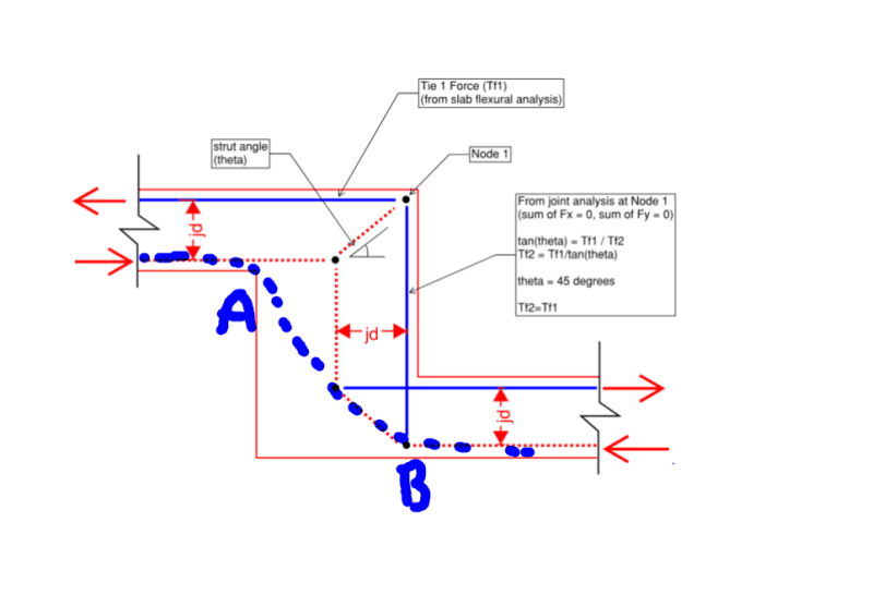
I also disagree with the validity of the STM model shown below. An appropriate STM model needs to at least approximate the real state of stress within the element being modelled. And I would submit that the real state of stress would involve a compression field connecting points A & B somewhat directly which leads to the utilization of more of the step width.

C01_fpxva3.png
 
Koot said:
I somewhat disagree. The tension that this would produce on one side would be offset by compression clamping on the other side of the beam...

Okay - I can buy into that.

Koot said:
In my experience, nobody actually designs slab steps via strut and tie...

Totally - agreed, I wanted to answer the question about whether it's acceptable to assume flexural behavior through the joint and wanted to emphasize that technically no, this is a D-Region, however via some simplified assumptions you can just assume a similar effective depth(width) of that step and use the same bars as required for negative moment in the slab.
This is conservative, but also fast and stupid.

Koot said:
In my experience, nobody actually designs slab steps via strut and tie.
Good to emphasize. In all practical cases I'm not making STM models for the slab steps I'm designing.

Koot said:
I agree. In my experience, none of the details wind up being fully STM compliant at a number of the nodes, and for a number of reasons. As I mentioned above, however, I've made no attempt to make the details fully STM compliant as that tends to produce results that the market finds unreasonable.
That's valid, we seem to be able to get away with z-bars for our slab steps as that detail is included in our set of typical details (lucky us!).

Koot said:
I also disagree with the validity of the STM model shown below.
Yeah... this model was really just to justify my dumb-but-quick suggestion to match the vertical tie force to the horizontal tie force.
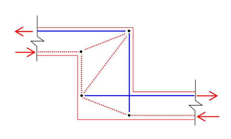
I think the "real" model looks more like this:
Slab_Fold_STM_lnaxej.png
 
dijon said:
Yeah... this model was really just to justify my dumb-but-quick suggestion to match the vertical tie force to the horizontal tie force.

I certainly agree on the matching when it's a continuity situation rather than a true beam situation.
 
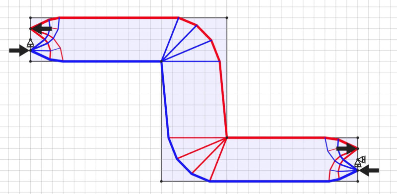
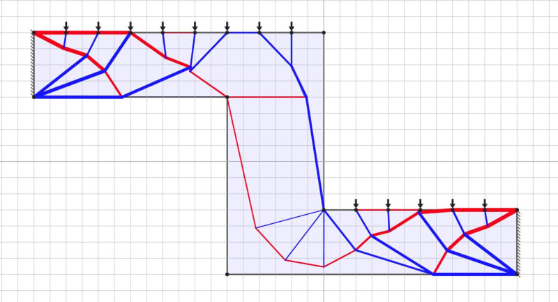
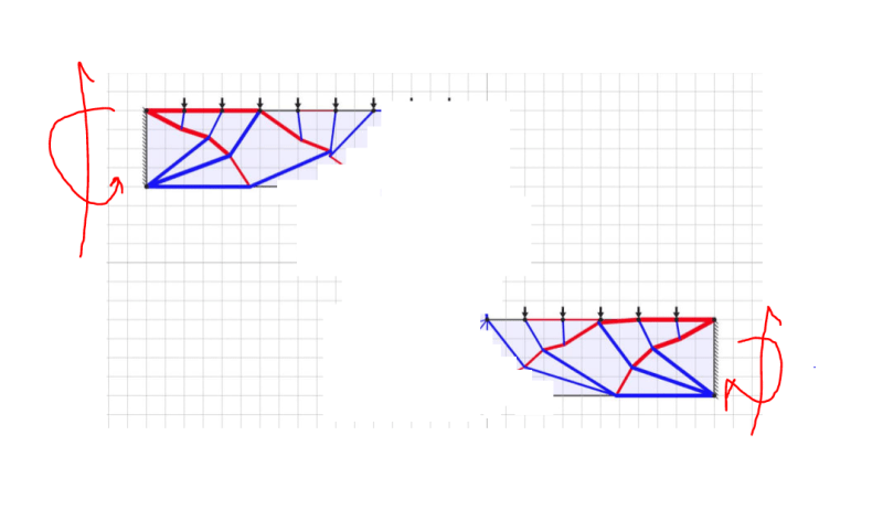
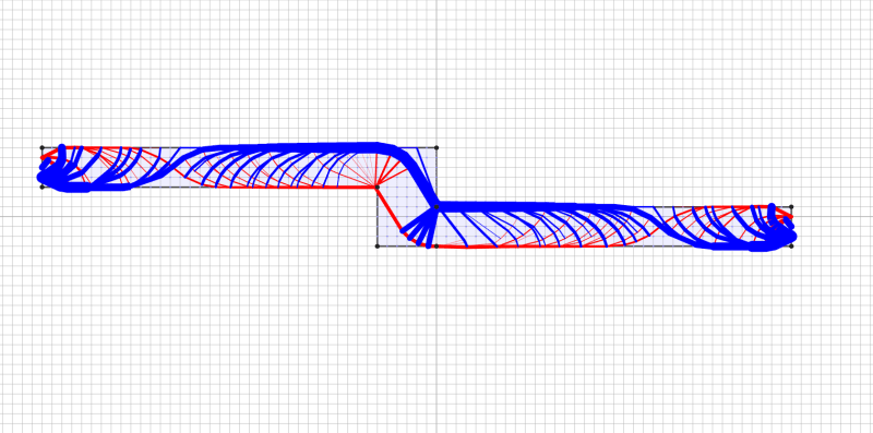
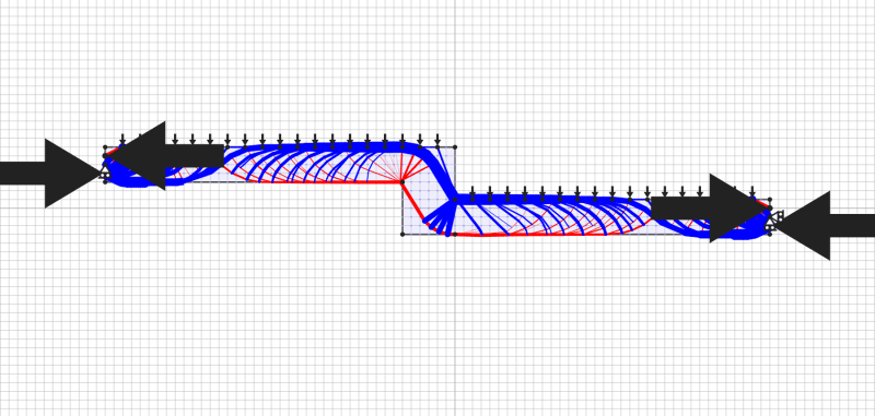
I've attempted the strut-tie-approach before what always gets lost is the impact that the loading on the slab has to the model, I threw this in a Truss optimization app, Link, that was posted here awhile ago and you can see how the tension and compression flips with the effect of a uniform load applied along the top surface:
T&C couple only:
Capture_couple_xoxjav.jpg


Uniform loading along top surface:
Capture_loaded_rj98vm.jpg
 
Celt83 said:
I've attempted the strut-tie-approach before what always gets lost is the impact that the loading on the slab has to the model, I threw this in a Truss optimization app, Link, that was posted here awhile ago and you can see how the tension and compression flips with the effect of a uniform load applied along the top surface:

I don't buy it. Problems with the uniformly loaded model:

1) The slab lengths that you've modelled are ridiculously short relative to the proportions of the step.

2) This model provides axial restraint at the ends of the slabs which likely don't exist and will impact the stress fields.

Properly modelled, I expect that the T&C model would be the more salient.

Your uniformly loaded model is, effectively, one big disturbed region.
 
dijon said:
I typically see them detailed like in my attached sketch.

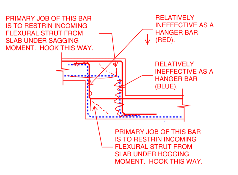
As shown in the sketch below, I feel that there are aspects of that detail that are both wasteful and ineffective. I don't say this just for the sake of being confrontational but, rather, because:

1) As always, I'm most interested in pursuing consensus based truths where they are achievable and;

2) I like interesting theoretical discussion and I see an opportunity for that here and;

2) Perhaps this may benefit your practice. Or mine if I'm out to lunch.

The key "truth" that I feel warrants discussion here is this: when the hook direction of a bar in a strut in tie model is ambiguous, precedent should usually be given to a flexural member's tension steel hook being oriented to restrain that same member's incoming shear strut. This is almost always the primary source of demand at an anchorage condition in my experience.

C01_rrrxgs.png
 
When I look at that model with the uniform load, what I see is two cantilevers. That the stresses reverse at the step is immaterial since that's not where the real action is anyhow.

C01_o6n2xx.png
 
I'm really confused with where this discussion has ended up. For a spanning beam with a step in the middle surely it won't actually have a fixed end
The most normal situation I can think of for this is a grillage of beams over say a basement
The end of the spanning beam will most likely frame into perpendicular beams at each end
The torsional stiffness of these beams will probably be low, so the attempted fixed-end restraint will cause them to crack out and the spanning beam default to a simply-supported beam
In this case the step in the middle becomes critical to ensure stability
Why would this not just be designed with the 'Cadillac' solution?
 
KootK said:
When I look at that model with the uniform load, what I see is two cantilevers. That the stresses reverse at the step is immaterial since that's not where the real action is anyhow.

Doesn't this align with what the inflection point of a fixed-fixed beam would look like?

I agree the model scale is not accurate but I interpreted the above sketches to mean the fold is within the fixed-fixed span so for a uniformly loaded condition I would expect the tension field to be at the bottom towards midspan and the top towards the ends.

Truss_bc5k8z.png


Truss2_zdn7jk.png
 
Celt83 said:
Doesn't this align with what the inflection point of a fixed-fixed beam would look like?

It does but, then:

1) At the inflection point, by definition, you're talking about a slab step at a location where no moment needs to be transferred across the step.

2) I would consider a "no moment" situation to be a poor representation of the principles that we're trying to discuss here.

Your latest batch of models, it seems to me, is much more representative of behavior and simply confirms our original assumptions.

Celt83 said:
..what always gets lost is the impact that the loading on the slab has to the model

Without pulling any punches, I feel that observation is unsubstantiated. Consider:

3) In your latest model, it appears to me that consideration of the loading has changed nothing.

4) The earlier models where consideration of the loading did change something are not representative of the phenomenon being discussed (according to me at least).

Your observation would lead readers of this thread to question the validity of the detailing that we've been working out here. I, for one, don't want that doubt creeping into our work unless it's justified.

 
Celt83 said:
...the fold is within the fixed-fixed sptan so for a uniformly loaded condition I would expect the tension field to be at the bottom towards midspan and the top towards the ends.

Yes, but the reversal is unsurprising and would be deduced simply from an inspection of the slab moment diagram, right? And that moment diagram would have the nature of the loading baked into the cake.


apologize I'm a bit off base here. I was getting caught up on KootK and dijonnaise showing strut-tie models based on the opposite curvature I would expect based on OP's description but I realize now that is exactly the moment configuration OP presented.
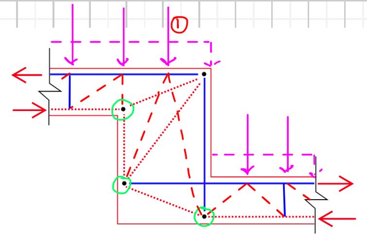
Keeping to the moment direction as presented with the addition of the applied loading I feel at least the circled nodes would have additional demand vs just looking at the internal tension compression couple on either side of the fold.
Capture_loaded_anhaza.jpg

I don't believe the struts I have coming off of the discretized point load labeled 1 are entirely accurate.
 
Celt83 said:
I feel at least the circled nodes would have additional demand vs just looking at the internal tension compression couple on either side of the fold.

Yes, but it's a question of scale. Certainly, for a uniform slab load, that effect would get lost in the noise of:

a) the flexural demand creating much larger internal forces and;

b) the shear struts coming in from either side of the step which would dominate and are already considered.

If there were a massive point load right over the step ( masonry bearing wall etc) then, sure, that might warrant some special consideration. But, then, this would again be a non-representative case in my opinion.
 
Kootk said:
I don't say this just for the sake of being confrontational but, rather, because:

No worries on this front at all, I read enough of your posts in my earlier career to know where you're coming from.

I realized that I misrepresented our own detail. Those exact bars that you commented on are only indicated to be as wiggly as they are to illustrate the condition where a standard hook might be too short for an embedment length, perhaps for very large bars or a very narrow step. Likely we end up with what you've drawn in most cases.
 
dijon said:
No worries on this front at all, I read enough of your posts in my earlier career to know where you're coming from.

Excellent. For once, it's good to be a known quantity.

dijon said:
...as they are to illustrate the condition where a standard hook might be too short for an embedment length

That kind of speaks to my point though. If the hooks are turned the "right" direction -- according to me at least -- then they will always be turned into the body of the slab element from which the bars originated. If the 90 hooks are too long, then one of two things happen:

1) 180 hooks if you can get away with it.

2) Tilt the hooks if you must.
 
KootK said:
Certainly, for a uniform slab load, that effect would get lost in the noise of
yeah agreed the relative magnitude of the internals forces should dwarf the uniform load discretized points for the typical condition.

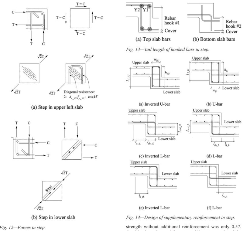
to be more helpful I was able to find all of 1 article on this in the ACI Structural Journal if anyone is interested:
Capture_loaded_hy64mw.jpg


Which recommends the following bar arrangement:
Capture_loaded_kotupp.jpg
 
Yeah, I've got that one (as you know). At the risk of sounding like -- and possibly being -- a raging egomaniac, I feel that the authors don't know what they're talking about it a lot of ways. I like their testing of some common configurations but much less their recommendations for improvement. A PhD does not an engineer make I'm afraid.
 
Status
Not open for further replies.

Part and Inventory Search

Sponsor