Continue to Site

Eng-Tips is the largest engineering community on the Internet

Intelligent Work Forums for Engineering Professionals

  • Congratulations KootK on being selected by the Eng-Tips community for having the most helpful posts in the forums last week. Way to Go!

Detailing of required reinforcement with slab offset 2

Status
Not open for further replies.

chritsar

Structural
May 9, 2022
11
Suppose we have a slab with an offset that at the same time acts as a supporting beam (happens a lot in projects where there is an underground garage for example). In the static analysis the slab is assumed to be continuous. The beam acts as a support therefore the moments in the slab will be negative requiring top reinforcement.

The question: Is it enough to anchor the top reinforcement inside the width of the beam? Or is it necessary to overlap the required reinforcement with the beam stirrups in order to provide continuity of the moment resistance between the top and bottom slabs?

By my estimate, this has to do with the width of the beam (b in the sketch). In sufficiently wide beams (how would that be defined though?) the beam can be assumed as fully rigid and therefore I would expect a mere anchorage of the slab reinforcement to suffice. If the beam is not wide enough (perhaps close to the depth of the slabs) then I would expect a need for overlapping the required reinforcement of the slabs with the beam stirrups so the moment can be fully transferred.

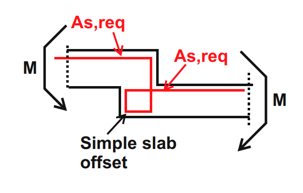
Below I have two sketches: One is the described situation - slab offset as a supporting beam and the second is a typical slab offset with the proposed reinforcement for moment continuity.
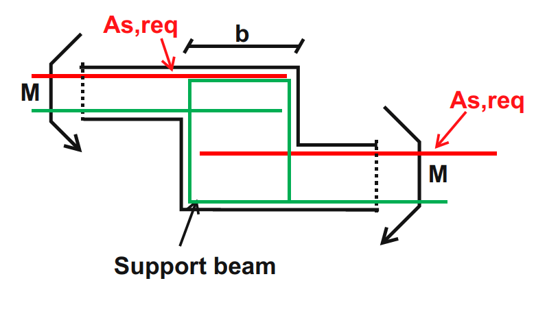
Support_beam_-_offset_tb25zr.png

Simple_slab_offset_dbtclp.png
 
Replies continue below

Recommended for you

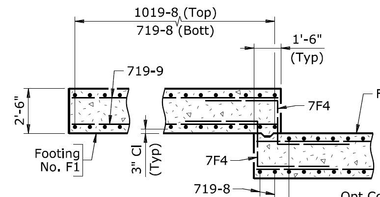
An interesting discussion. Just to add a little more fodder for discussion (though it seems there is plenty already), my arrangement for the footing steps in a rather large retaining wall looked like this:

step_footing_duyweu.png


Rod Smith, P.E., The artist formerly known as HotRod10
 
Oi... it seems that this will be the thread where I alienate the few remaining friends that I have left.

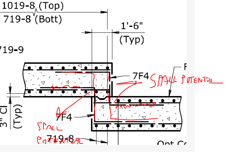
I don't like z-bars that don't make it to the far face of the members into which they are embedded. As shown, the bars would create spalling potential that would render the bars pretty useless in tension. And, at the end of the day, why bother installing a bar if you can't pull on the damn thing?

C01_ucpdue.png
 
Oi... it seems that this will be the thread where I alienate the few remaining friends that I have left.

I don't like z-bars that don't make it to the far face of the members into which they are embedded. As shown, the bars would create spalling potential that would render the bars pretty useless in tension. And, at the end of the day, why bother installing a bar if you can't pull on the damn thing?

No worries about alienating me. I greatly respect your insights, and I agree with you. I completely overlooked that potential failure mechanism.

Lucky for me, the contractor opted for a different type of wall, and had a consultant design it. The footing I showed was for a post-tensioned wall utilizing precast double T sections for the stem. The contractor proposed (and we ultimately accepted) an all CIP wall. It's a monster - up to 30' high and 900' long, with an upper tier MSE wall up to 15' high above it.

Rod Smith, P.E., The artist formerly known as HotRod10
 
KootK said:
I don't like z-bars that don't make it to the far face of the members into which they are embedded.

Beat me to the punch it seems, that's the first thing I noticed too.
 
One warning for those who are trying to maintain capacity through the top face and vertical face of the step, it is "capacity" you need to maintain, not area of steel.

- If the throat thickness is larger than the slab depth either side, the area of steel can reduce to maintain moment capacity.

- if it is prestressed, then it is a completely different calculation. If the PT is not continuous, the Area of steel required will need to take the full moment, while in the slab the PT will be contributing. Even if the PT can be continuous, unless it is a very long step transition effectively making it a sloping slab rather than a step, the PT will have no effect on the vertical reinforcement. So you could end up with a lot more vertical reinforcement than slab face reinforcement.
 
BridgeSmith said:
Lucky for me...

No luck required. While it might be a technical detailing fail, it would have been a very low consequence one. When I see this on footing step details, I speculate that the designer is often simply attempting to make the T&S rebar continuous across the step which is understandable. And, often, there isn't space available for a "by the book" detail. Heck, I think that my own residential footing step detail shows it this way.
 
Yeah, considering the forces on the footing should be fairly even across the joint (the stem sections would be made continuous by shear keys) moment transfer, and even shear transfer, across the step would be minimal. You've definitely made me think, though, and I've learned something today, both of which are good things.

Rod Smith, P.E., The artist formerly known as HotRod10
 
Status
Not open for further replies.

Part and Inventory Search

Sponsor