Continue to Site

Eng-Tips is the largest engineering community on the Internet

Intelligent Work Forums for Engineering Professionals

  • Congratulations KootK on being selected by the Eng-Tips community for having the most helpful posts in the forums last week. Way to Go!

Diagnose Broken Shaft 8

Status
Not open for further replies.

_Christos_

Mechanical
Feb 12, 2024
3
1706872245976_vgyaia.jpg
1706872245896_ntlrdd.jpg
1706872245849_suawkp.jpg
1706872245705_kp9rza.jpg
Hello ladies and gentlemen,
I hope everyone is well!

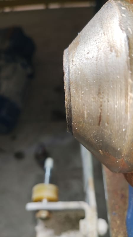
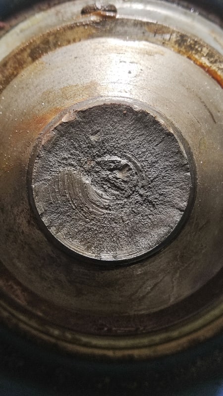
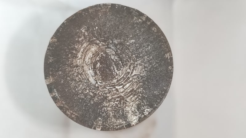
Can you help me diagnose the failure of this broken shaft?
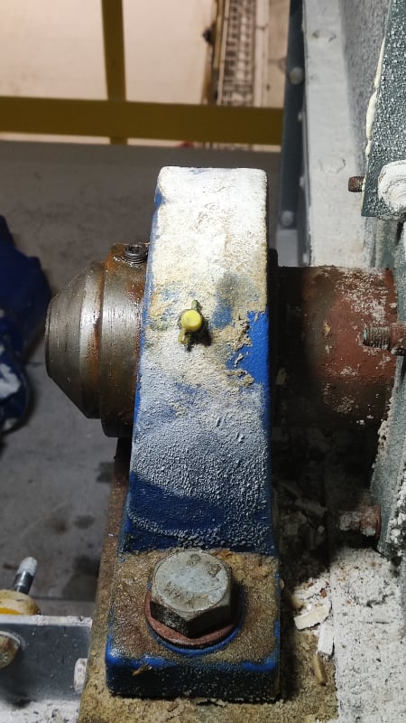
This was on a bucket elevator, a gearmotor drove the wheel of the elevator through this shaft.
My preliminary findings suggest that this failed due to bending fatigue because the weight of the gearmotor was not adequately supported on the body of the elevator.

Can someone confirm this diagnosis or point me in the right direction?

I have attached photos of both sides of the break and of the broken off shaft on the machine before we took it out.

Thank you for reading!

Edit: I hope the attached images are visible now.
 
Replies continue below

Recommended for you

Hi Christos

There are no attachments?


“Do not worry about your problems with mathematics, I assure you mine are far greater.” Albert Einstein
 
Fatigue. Stresses might be acceptable on paper but the transition down to the final diameter is garbage in finish and design.
 
I agree with the previous comment. High cycle fatigue caused by misalignment of the shaft bearings. Essentially, the shaft was "flexing" as it rotates and the crack propagation started at the corner of the reduced diameter.

Shafts sheared by high torque have a different shape caused by the distribution of the strain along the axis.
 
That shaft design was just waiting to fail. The machined corner is a natural stress concentrator. Consider a coupling for transition from large to small diameters.
 
definitly fatigue and primarily due to transition desighn perJboggs.
 
Pictures of the other item in the 'train" would be helpful.

The gear motor has a hollow shaft to engage the piece of the shaft that is missing?

I've seen concentric gear reducers that are supported 100% by the shaft.
Plenty of devilish details on those things.
One more component that is not a good candidate for FOAK brochure engineering in my opinion.

, but the few hollow shaft gear motors I've seen have been face mounted.
The support and alignment were controlled by whatever the face is bolted too.
 
The downside of shaft mounted reducers is that you end up buying a bigger reducer if you want a large enough shaft to feel comfortable. The shaft failure may also be related to the torque arm being overly tightened and inducing a heavier bending load than just the reaction force of the reducer. Attached is some literature on resolving shaft mounted reducer forces.
 
 https://files.engineering.com/getfile.aspx?folder=d78d2de8-ef0c-4e7c-ab75-c5db369e8e13&file=White_Paper_-_Torque_Arm_-_Final_Edit.pdf
Thank you all for responding!

Desertfox, thank you for the link!

Tmoose, thank you also for the link, but it 403s on me, I don't have permission to access this document. I could not obtain pictures of the rest of the drive as i was not present when the shaft was switched out for the new one. You are right about the hollow shaft in the gearmotor, it's the shaft of the worm wheel. But it's not a concentric reducer in this case.

Geesaman.d and fluidpoweruser, I will take your suggestion into consideration. I am normally hesitant to modify OEM designs but in this case I might just do that for the spare shafts as I clearly see your point.

DvD, thank you for the read! I will discuss your idea with the OEM as we lengthened the elevator some 30% and we did seek their advice for upsizing the shaft & gearmotor. Good catch!


Christos you’re very welcome

“Do not worry about your problems with mathematics, I assure you mine are far greater.” Albert Einstein
 
My link was just a generic picture of a gear motor. Now an attached jpg.

Are there pictures of the new shaft showing the region that broke preiously.
I'd expect if this is //really// a mature product the shaft transition detail would have evolved to include MUCH fancier more thoughtful geometry, possibly an upgraded materteral and possibly even a treatment like shot peening or a rolled fillet.

If the replacement shaft design did NOT include significant technical improvements I'd be most reluctant to run it for long.

Did we hear how long the busted shaft was in service ?
 
 https://files.engineering.com/getfile.aspx?folder=1bd6547a-d8a9-46d6-96cb-3d40f67fd0e5&file=ac_3_phase_inverter_duty_-_42r_5lh_series_3_phase_gearmotor.jpg
"It was in service since August 2023."

The machine looks like it has been in service long before that.

Why was the previous shaft replaced?
Did the previous shaft also break?

Was the recently failed replacement an OEM part, or fabricated locally?
//OR// was the recently broken shaft "repaired" perhaps by welding on a "new" end that engages te\he coupling ?
 
Status
Not open for further replies.

Part and Inventory Search

Sponsor