Eng-Tips is the largest engineering community on the Internet

Intelligent Work Forums for Engineering Professionals

difference between composite and multi segment pos tol in asme y14.5 2009 5

Status
Not open for further replies.

Gopinath K

Mechanical
Jul 5, 2023
13
0
0
IN
Hi All
Can any one explain exact difference between composite and multi-segment pos tolerance, is Multi segment used for refinement of uppersegment ?
in both lower segment controls orientation and feature relation then what is the difference and how to choose which one to use with same datums.
refer images from asme y 2009 and list the difference pls
image from fig 7.39a and 7.46 c
 
 https://files.engineering.com/getfile.aspx?folder=d1a254b5-0999-4a3c-8eda-8566d4e384be&file=composite_tol.PNG
Replies continue below

Recommended for you

Composite upper locates the pattern of features to the datums.
Composite lower locates the individual features in pattern to each other.

Multiple segment upper locates the pattern of features to the datums.
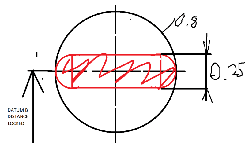
Multiple lower segment fixes distance to datum B as basic. No allowance. In this particular case.
 
Hi 3DDave
Thank you for response.
if Multiple lower segment fixes distance to datum B as basic in this case
In standard i see lower segment controls rotation and translation (basically located). what does allowed translation with respect to Datum B
my only doubt is when secondary datum is specified in lower-segment of composite and multi segment FCF.
 
In fig 7.46 c
does pos tol 0.25 in lower segment provides pos tolerance for 125 basic dim from datum B or not ?


as per Wuzhee words
Multiple lower segment fixes distance to datum B as basic. No allowance. In this particular case.

what does no allowance means center of pattern holes did not have any location deviation from datum B
 
In case of multiple segment, the lower segment fixes the distance at 125 from Datum B. the 0.25 tolerance zone can translate inside the upper segments tol. zone but can't translate in any other direction.
Check out these amazing sample drawings:
COMPOSITE:
comp_iafhcx.png

MULTIPLE SEGMENT:
MULTI_n3jwuw.png
 
In the composite FCF the upper segment limits the features within the specified tolerance in translation and rotation in the degrees of freedom constrained by the datum references (location & orientation are controlled). The lower segment only limits the variation in the relationship of the holes to each other per the basic dimensions connecting them, and in rotational degrees of freedom relative to the datums (orientation only is limited relative to the datums, and within-pattern location & orientation is controlled).

A multiple single segment FCF is essentially just two or more separate FCFs. The features in the pattern are limited in rotation and translation relative to the datums in each of the segments. Therefore, when a multiple single segments control is used, you never repeat the exact same datums in the same order as in the upper segment, for the lower segment. The lower segment is a tighter control but with fewer degrees of freedom constrained, therefore some translation or rotation of the lower segment tolerance zones will always be allowed, to enable  "fitting" (moving the part features into their tolerance zones).

In both cases, the lower segment is a refinement.
 
"my only doubt is when secondary datum is specified in lower-segment of composite and multi segment FCF."

This is clearly explained in the standard. What words and pictures in the standard are doubt.
 
I am tempted to write some large amount to explain the difference, but there is already quite a bit written in those images and the paragraphs they reference.

I am also sure someone else will come along and explain the exact difference for exactly this case and you may go "Oh, I understand this case now."

But if you have already read the basis of composite tolerances and looked at all the other examples and still don't understand this one, then providing this answer will interfere with you actually understanding how datum references and datum reference frames work.

I suggest you go back to simpler cases and work out how they work instead of having someone patch over a gap in your learning, a gap that will cause you trouble later on.
 
Gopinath_K said:
I got doubt in radial hole pattern in both , pls find attachment
I did not find much difference between two images.

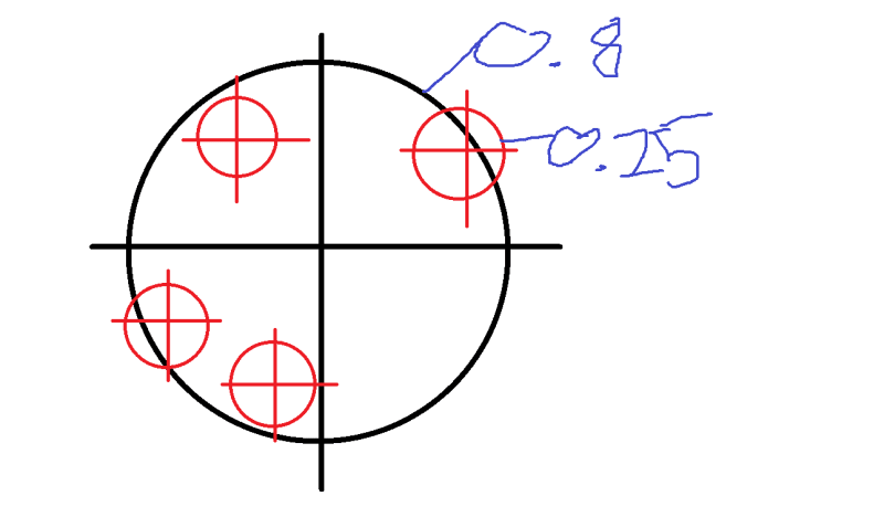
On the left hand side, if you take a closer look at the cross created by the center lines of the pattern of smaller tolerance zones, you should notice that it is not at the same distance from datum plane A as the cross created by the center lines of the larger tolerance zone pattern. Also, only the center of the latter cross is located on datum axis B. This is all because of the composite position tolerancing rule basically stating that lower segment(s) of composite callouts do not locate features/tolerance zones relative to the specified datums, they are only able to orient.

On the right hand side, the pattern of smaller tolerance zones is oriented and located relative to the specified datums, therefore it is located relative to datums A and B in the same way as the pattern of larger tolerance zones is. The smaller pattern may, however, rotate around datum axis B becasue C is not referenced in the lower position feature control frame.

As 3DDave said, this is not the best example to grasp the basics of the composite vs. multiple segment tolerancing topic.
 
I understood that
The lower feature control frame is segment 2 also where two datums control the orientation and alignment

in figure looks like axis of smaller tolerance zone (segment 2) of Multi-segment FCF is not falls in pattern center location dimension 14 from Datum A.
center point is intersecting but it looks zone of 0.25 is not in line with 14 dim.
where is in other figures secondary datum is with in smaller boundary to specified datums.
.
I just want to know thoughts of others on this
Thanks for your support
 
Gopinath K,

I agree with pmarc's description, and I agree that this is a difficult example to visualize.

In the first figure for the composite FCF, the lower segment tolerance zone framework has translated but not rotated. It looks like the zones have moved in the direction away from datum A (so their distance from A is larger than 14). They have also moved a bit downward.

In the second figure for the single segment FCF's, the lower segment tolerance zone framework has rotated but not translated. It looks like the zones have rotated about datum axis B, in the counterclockwise direction. Their distance from A is still exactly 14.

Evan Janeshewski

Axymetrix Quality Engineering Inc.
 
Gopinath said:
in figure looks like axis of smaller tolerance zone (segment 2) of Multi-segment FCF is not falls in pattern center location dimension 14 from Datum A.
center point is intersecting but it looks zone of 0.25 is not in line with 14 dim.
Please draw on the figure and show how you would expect it to look, if the zones stayed exactly 14 away from datum plane A, aligned with datum axis B, and only rotated about datum axis B.
 
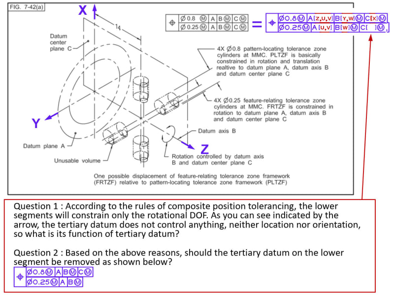
Season - FOR THE LOWER SEGMENT ONLY: since datum AXIS B is nominally perpendicular to datum PLANE A, then it is redundant and controls nothing. datum PLANE C does control the rotation that datum PLANE A/datum AXIS B do not control.
 
Ditto what 3DDave said. The degree of freedom [w] is constrained by datum C, not datum B.
However, datum B(M) is still referenced to maintain the primary/secondary/tertiary precedence.

John-Paul Belanger
Certified Sr. GD&T Professional
Geometric Learning Systems
 
Thanks for your prompt comments, 3DDave and JP
Corrected as shown:

2023-08-10_232555_ycuqnl.jpg


In this case, secondary datum will control nothing on the lower segment, will ask the same question : What is its function of secondary datum?

Edit: Understood.[highlight #EF2929][/highlight]
3DDave said:
it is redundant and controls nothing.

Season
 
Status
Not open for further replies.
Back
Top