Eng-Tips is the largest engineering community on the Internet

Intelligent Work Forums for Engineering Professionals

Different interpretations of the DATUMS - Which is correct? 1

Status
Not open for further replies.

J-Hendry

Mechanical
Jul 16, 2021
10
0
0
GB
Hello all,

I hope this is posted in the correct place.

I am currently going back and forth with one of our engineers regarding how I read the drawing and the setup for inspection to the engineer who has revised this drawing (Not the original drawer).

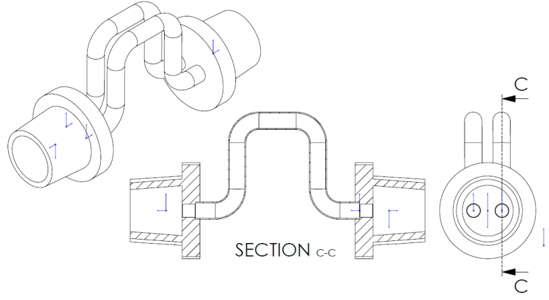
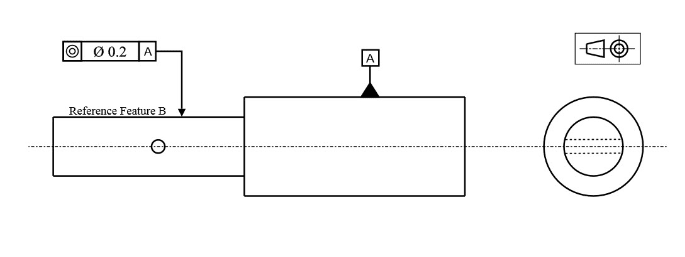
Below is a roughly drawn part, fairly similar to what I'm working with.
Drawing_snag_dh0wzc.png


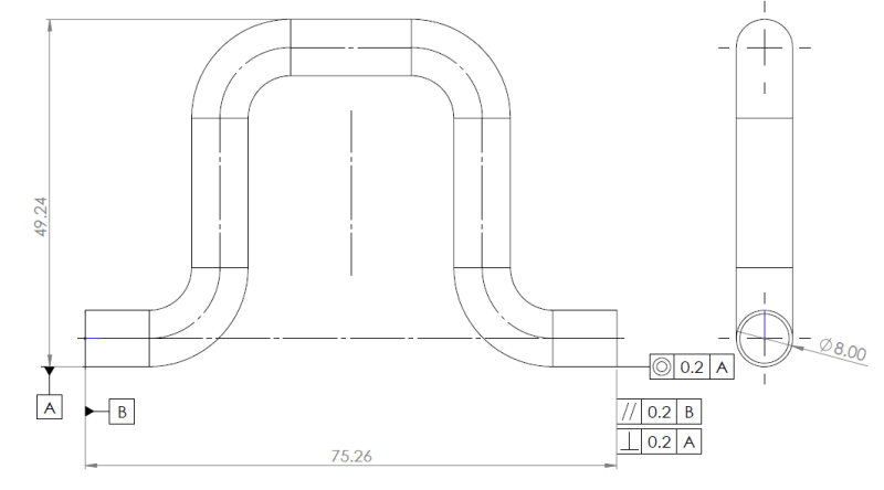
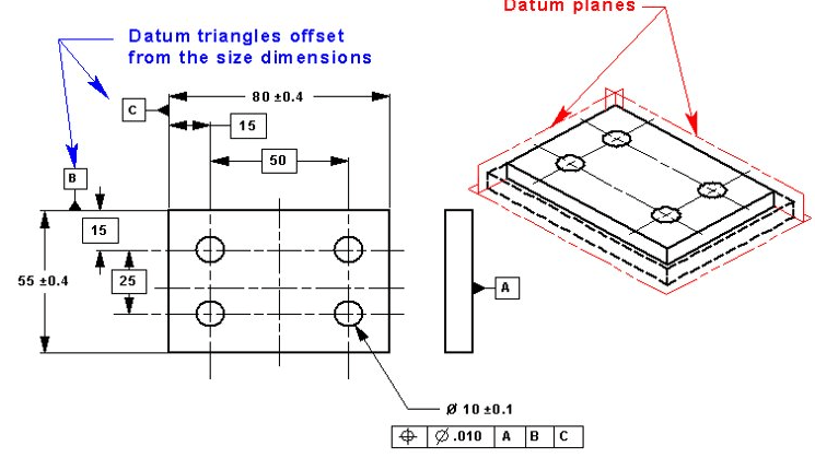
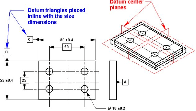
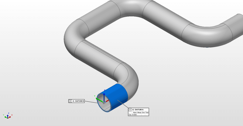
The way I read this drawing is: DAT A is the cylinder it's connected to and DAT B is the end plane - As the image displays below.
Interpretation_of_datums_gorar4.png


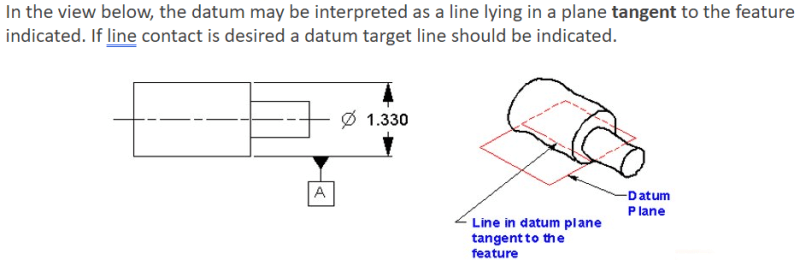
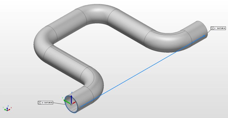
I have queried the DATUM intent from the engineer and he has told me that this is supposed to be read as DAT A being a line taken from the "Highest point" of this tube side profile across both parallel cylinders and DAT B as the end plane. - As the image displays below
Engineer_request_cvgecw.png


So we're both on the same page (fairly obvious) with DATUM B. It's DATUM A that is confusing. We're working to ISO 8015. I have been reading up on this throughout the day and I believe for the drawing to read how it was intended, the line requested should be marked with DATUM target points creating a DATUM target line.

Could anyone share their thoughts on this either as a design engineer or quality inspector?

Thanks
 
Replies continue below

Recommended for you

forum1103 may be a better forum for this question

"Know the rules well, so you can break them effectively."
-Dalai Lama XIV
 
ASME Y14.5-1994 said:
1.3.3 Datum. A theoretically exact point, axis, or plane defiled from the true geometric counterpart of a specified datum feature. A datum is the origin from which the location or geometric characteristics of features of a part are established.

So, your interpretation cannot be possible. Datum A cannot be referenced from something else in the drawing that is not a datum, but that's a semantics thing, i.e., the highest point is referenced from datum A, not the other way around. The concentricity seems misapplied, since datum A is most likely a plane, particularly since the highest point is measured from it.


TTFN (ta ta for now)
I can do absolutely anything. I'm an expert! faq731-376 forum1529 Entire Forum list
 
Apologies, the datum A should be offset from the distance leader line.

By me saying DATUM A I see as the cylinder I mean the cylinder axis incase I've left any confusion.

What plane is it you're seeing as DATUM A? I see it that the concentricity/coaxility callout has just been placed in a way causing ambiguity and should be the opposing cylinder thats coaxial to the one marked with datum A.
I cannot make no sense of the coaxial callout if a line is supposed to be created along both of the cylinder sides for datum a? Where is the start and end of this line to measure against the referenced datum?

I've always understood the axis of cylinders to be the datum unless stated otherwise through target points? I could be majorly off but I don't believe this differs from ISO + ASME?
 
It is worth noting that, given the cylindrical features involved, that there is an assumed orientation of the part. Assumptions of this type often go unnoticed because the inspector will usually just drop the part onto the granite slab and start to work. However, contact with the granite slab establishes a datum feature that is not mentioned anywhere on the drawing.

This should be explicit and, in the case of formed tubing, might benefit from setting up datum targets to avoid the part rocking during inspection so that sequential parts can be rapidly validated.
 
Hi 3DDave,

In response to your first reply i can see the asssumption of this being the width dimension although i did post that this was in the incorrect position and should be offset from the distance. As updated below:
Extracted_pxxmcq.png


I've understood for this to be only the contacted surface considered for the datum when the datum is offset from the distance leader, as shown below:
Leader_offset_mfcoyx.png

Leader_in_line_qubvaa.png
 
To follow up on my message yesterday
J-Hendry said:
I have been reading up on this throughout the day and I believe for the drawing to read how it was intended, the line requested should be marked with DATUM target points creating a DATUM target line.
This image below shows a similarly dimensioned part but mine doesnt have the diameter dimensioned in this position - Although it does have the diameter in the other view
Side_of_cylinder_zycpnd.png
 
It's round so any tangent on the round surface can be [A]. It's assumed to be also perpendicular to the viewing direction, but that isn't well defined. Like, picture holding the part and eye-balling which of many tangents is the one tangent you need. So the part gets placed on a granite slab and the orientation isn't set by a reference on the part, but because the CMM operator just chose that way to put it.

In the cases you show, the flat faces have a unique orientation, so that works, and references such as [A|B] assume that B is perpendicular to A; but A is flat.

In this case the tangent is not oriented to anything. So picture the part setting with that U-shape up away from the granite slab and the CMM operator balancing it. Nothing holds that tangency in place.

Finally - concentricity cannot apply relative to a plane and it's sketchy to apply it to a tangent line rather than a diameter indication for a round tube.

Is there a functional goal for these features? Just giving the two end segments a common profile of surface tolerance would set the allowable variation much better. Even a position tolerance would be more in keeping with the usual functional goal.
 
Thanks for your input 3DDave,

Unfortunately im still confused if this is dimensioned in the intended way by the drawer.

I have put together a quick assembly which replicates the actual use of these parts here. Im not sure if this will give a better understanding of the initial component from this.

Assembled_benty_tube_gzo4zi.png
 
Then either position or profile can be used. You can also indicate that the small areas on the ends are the only portions that matter.

Your followup with tangent line came while I was typing, so I did not see it. The problem in that is that every tangent line all around the fitting has a plane - there are an infinite number of orientations that concentricity doesn't apply to.

You should be confused because the drawing doesn't make sense.
 
Thanks again for your help on this 3DDave.

The engineer has come back now acknowledging the drawing isnt up to scratch for the intentions. Im still struggling to understand how the DAT A isnt considered a cylinder in the way its been dimensioned on the drawing as its fairly similar to this image below, although the referenced feature is connected to the Datum this is dimensioned the same as the part im working with.
Concentricity_dimensioned_wjcsn8.png


Do you know how i'd go about transferring this to the forum section mentioned by ewh? (Drafting Standards, GD&T & Tolerance Analysis)

Thanks again.
 
The datum feature symbol can be moved to the diameter dimension and be entirely unambiguous.
Is there some reason to remain ambiguous?

Use to describe the size at one end with the areas that interface to the mating parts marked A:

2X Tube diameter MARKED A
[position tolerance|(dia) tolerance MMC]

where tolerance is the amount of diametral clearance allowed by the mating part at its MMC condition

and that will create a simultaneous requirement for the two ends.

In addition, both ends fix the orientation of the part so it should be that each diameter gets a diametral indication, rather than tangential, of a datum feature symbol, such as [A] and and then the perpendicularity would be to [A-B].

---

Concentricity is the worst choice for this feature control. I'm confused that anyone would choose to use it.

What is especially sucky is that the orientation of datum feature B relative to datum feature A is driven by the parallelism tolerance on the other face, a face that is also controlled by perpendicularity to Al this complex chain rather than making both ends being perpendicular to A.

Try clicking "Report" on your first entry and ask the engtips owners if they would move it.
 
Hi, J-Hendry:

Your data feature A (be it cylindrical or line segment) is too short to qualify as a primary datum feature. You will need common datum features to define datum A. I don't know if common datum feature is a valid term in ISO 1011. In ASME Y14.5-2018, it is at section 7.12 (page 77). There should be something similar in ISO.

Common data features mean that both ends (cylinders) are used together to establish datum.

Best regards,

Alex
 
Status
Not open for further replies.
Back
Top