Eng-Tips is the largest engineering community on the Internet

Intelligent Work Forums for Engineering Professionals

Does this bolt see bending or not? 1

Status
Not open for further replies.

Vitkacy1989

Structural
Dec 8, 2012
54
0
0
DE
Hi all,

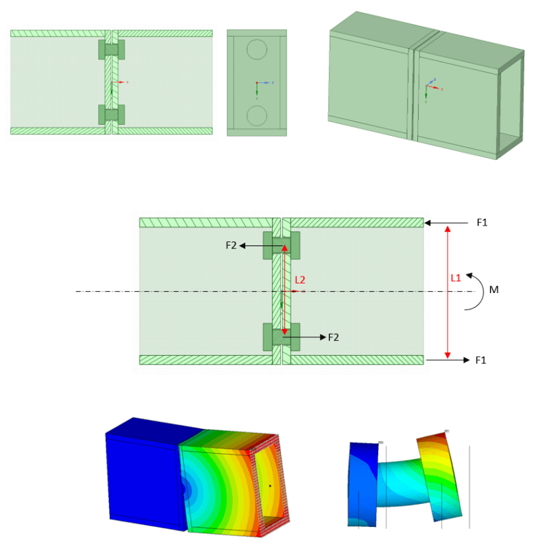
Picture below explains the system. I have a solid model with moment load at one side and fixation at other. Two tubes are connected with two bolts to check moment transfer. F2 is obviously larger than F1 due to different levers lengths.

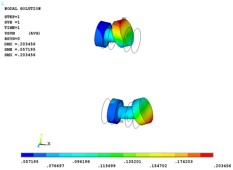
FEA shows high stress at bolt's shaft mainly due to bolt bending. And now I just thought, if I would calculate this connection by hand, that bolt would see no bending at all, just the stress from F2 tension. But in FEA, we get enormously higher stress due to bending alone.

Am I missing some moment at bolts in my free body diagram? Why hand calculation results and FEA are different?

Q1_cs7gxj.png
 
Replies continue below

Recommended for you

There are a few things that look a bit off with your contour plot.

Why is the beam on the left hand side not seeing any stresses?
The image isn't clear, but it appears as though the right hand side beam is penetrating the left hand side beam at the top? Do you have frictional contact created between the two end plates?
Did you apply a pretension load to the bolt?

Additionally, there isn't much information about the setup of the model. What sort of boundary conditions do you have? How was the moment applied (I assume you used a remote point?). Additionally, this seems like a fairly straight forward calculation - as you stated, you already have design calculations by hand, why are these not sufficient?

Typically, bolt bending does not become a significant factor unless you have a really long fastener which is not the case in your problem. So the results do appear to be off.


The plot shows displacements. Left side displacements are small in comparison to the right side, but I agree that it should be the same actually.
There is no contact, I want to create just a test model, same reason no preload. Boundary conditions: all translations fixed at the left end surface. Moment is distributed via the remote MPC rigid contact (yes, remote point). I should look for a reason why left and right side do not have same displacements... Would you have any additional ideas? Thanks for help...
 
I have checked the model. Displacements on both sides are good.
The thing is that FEA captures bending in the bolt, while the same bending cannot be found out of simple hand calculation.
And as this simple model shows, bending in the bolt can cause significant tensile stress in bolt in addition to the axial stress from F2 force.
Question is if that bending should be used for a design of the bolt? If not, why not?
 
Can you post your hand calcs along with displacement plots from your model for both bolts? Is there a gap between the tubes? It looks like there is in the section view.
 
There is 1 mm gap to avoid mesh connection between the tubes.
Hand calculations: Load M=5kNm, distance between bolts L2=100mm, axial load per bolt F2=M/L2=50kN.
Displacement plots for both bolts:
Q2_wdawf0.png
 
Vitkacy1989 said:
I have checked the model. Displacements on both sides are good.
The thing is that FEA captures bending in the bolt, while the same bending cannot be found out of simple hand calculation.
And as this simple model shows, bending in the bolt can cause significant tensile stress in bolt in addition to the axial stress from F2 force.
Question is if that bending should be used for a design of the bolt? If not, why not?

The fundamental difference is that you're potentially comparing apples to oranges.

The hand calculations (which are based on a combination of first principles mechanics with physical testing validation) traditionally assume the parts are fully clamped, the bolts are pre-loaded, and rely on a plastic distribution to derive the forces you have shown in your free body diagram. You didn't apply any bolt pretension nor did you include contact between the two plates. I also assume that you didn't include any material non-linearity (since you didn't include other non-linearities with contact and the bolt pre-load).

Fundamentally, the hand calculation is conservative compared to the forces you should be getting with a more refined analysis or reality if you were to physically test this.

Next, think about the load transfer mechanism in your free body diagram. The line of action for the resultant tensile and compressive components of your moment is eccentric to the bolt - this generates a moment in your bolt. Again, as I mentioned in my initial post, bolt bending is not a factor unless you have a really thick ply (which you don't) or if you're getting some sort of prying effects (which you can't because you don't have contact between the parts).

 
STpipe, you've touched the exact point in your thinking above. FEA and hand calculation will provide two different results for forces in bolt. The problem is, in both cases I am using Eurocode 3 to validate bolts. Eurocode 3 does not have any formula to check bending of a bolt. Perhaps this bending is already included in bearing check (not sure).

You have said bending is not a factor - I have to ring a red bell for that one - FEA results clearly shows the bending is the main factor. So in the end, according to what code formulas would you design this bolt, being aware the main stress in this bolt is due to the bending effect?
 
If you don't include contact and pretensioning of the bolts in your analysis, then your conclusion that "FEA results clearly shows the bending is the main factor" is incorrect. It's the classic garbage in, garbage out pitfall of FEA. If you do not have a solid understanding of the mechanics involved with what you're trying to analyse, it will result in results that are meaningless.

As I mentioned, bolt bending is not a significant factor in the stresses that a bolt sees unless you have really thick plies, or unless you get into some prying effect. If it's the latter, then there are already code equations that take this into account already.
 
Could you tell me please how would you model bolt with what elements in case you would like not to use solid elements, no preload and no contact? It could be for example beam element with rbe3 or cerig as spikes, or revolute joint, etc. What is your best experience?
 
The answer to that question is entirely depending on what it is you are trying to achieve in the analysis. For a relatively small model where you're looking at a specific joint, then you would definitely look to apply the bolt pretension plus non-linear contact. For larger assemblies where you have many bolts, then you would look at simplifying how you do the connection. I would look at the following link for a very good description for the different methodologies you can use to model the bolted connection and the advantages and disadvantages of each approach.


Personally, considering that I have access to a fairly powerful computer, and it only looks like you're applying a single load case, I would just keep the model as you have it but ensure that non-linear contact and the bolt preload are included in the analysis. If you're not particularly interested in the stresses for anything but the bolts, then the runtime shouldn't be too long.
 
Status
Not open for further replies.
Back
Top